Ultra-High Vacuum Surface Preparation: Protocols, Optimization, and Validation for Advanced Research
This article provides a comprehensive guide to Ultra-High Vacuum (UHV) surface preparation, a critical process for research in surface science, pharmaceuticals, and advanced materials.
Ultra-High Vacuum Surface Preparation: Protocols, Optimization, and Validation for Advanced Research
Abstract
This article provides a comprehensive guide to Ultra-High Vacuum (UHV) surface preparation, a critical process for research in surface science, pharmaceuticals, and advanced materials. It covers the foundational principles of UHV environments, detailed protocols for various materials, strategies for troubleshooting and optimization, and advanced techniques for surface validation. Aimed at researchers and scientists, the content synthesizes current methodologies to ensure the achievement of atomically clean, well-defined surfaces essential for reliable experimental results in fields ranging from high-energy physics to drug development.
UHV Fundamentals: Principles and Material Considerations for Pristine Surfaces
Ultra-High Vacuum (UHV) describes a vacuum environment characterized by pressures lower than approximately 1×10⁻⁷ Pascals (Pa), 1×10⁻⁹ torrs, or 1×10⁻⁷ millibars (mbar) [1] [2]. This regime represents the ultimate evolution of high vacuum, creating conditions essential for advanced scientific research and industrial processes where molecular-level cleanliness is paramount. The fundamental importance of UHV lies in its ability to drastically reduce the number of gas molecules in a chamber, thereby enabling the creation and maintenance of atomically clean surfaces for extended periods [3].
In UHV systems, the mean free path of gas molecules—the average distance a molecule travels between collisions—exceeds several tens of kilometers [1]. This means that gas molecules are far more likely to collide with chamber walls than with each other, causing almost all molecular interactions to occur at surfaces within the chamber. Consequently, UHV conditions are indispensable for surface science experiments, where even minute levels of contamination can compromise results and invalidate experimental findings.
Quantitative Definition of the UHV Regime
Pressure Ranges in Vacuum Technology
Vacuum technology classifies pressure ranges based on physical behavior and technical requirements. The transition from high vacuum (HV) to UHV marks a critical threshold where different physical laws govern gas behavior and specialized techniques are required for pressure maintenance. The table below summarizes the standard vacuum classifications with a focus on the UHV regime and its bordering ranges.
Table 1: Vacuum Classification Regimes
| Regime | Pressure Range (mbar) | Pressure Range (Pa) | Dominant Gas Species | Primary Applications |
|---|---|---|---|---|
| High Vacuum (HV) | 10⁻³ to 10⁻⁷ | 10⁻¹ to 10⁻⁵ | Water vapor (H₂O) [2] | Thin film deposition, electron microscopy |
| Ultra-High Vacuum (UHV) | 10⁻⁷ to 10⁻¹² | 10⁻⁵ to 10⁻¹⁰ | Hydrogen (H₂), Carbon Monoxide (CO) [1] [2] | Surface science, particle accelerators |
| Extreme High Vacuum (XHV) | <10⁻¹² | <10⁻¹⁰ | Hydrogen, helium [4] [5] | Space simulation, fundamental research |
Gas Dynamics in UHV Environments
The exceptional properties of UHV environments can be quantified through key gas dynamics parameters derived from kinetic theory. These parameters highlight the profound difference between UHV and conventional vacuum environments.
Table 2: Gas Dynamics Parameters at Room Temperature (300K) for Nitrogen
| Pressure (mbar) | Gas Density (molecules/cm³) | Mean Free Path | Time to Form a Monolayer | Incident Flux (molecules cm⁻² s⁻¹) |
|---|---|---|---|---|
| 10⁻⁶ (High Vacuum) | ~3 × 10¹⁰ [6] | ~50 m [3] | Minutes to hours | ~10¹⁴ [6] |
| 10⁻⁹ (UHV) | ~3 × 10⁷ [6] | ~50 km [1] [3] | Several hours to days [3] | ~10¹¹ [6] |
| 10⁻¹² (XHV) | ~3 × 10⁴ [6] | ~50,000 km | Weeks to months | ~10⁸ [6] |
The incident flux (F) of gas molecules striking a surface is calculated using the Hertz-Knudsen equation [6]: [ F = \frac{P}{\sqrt{2 \pi m k T}} ] where P is pressure, m is molecular mass, k is Boltzmann's constant, and T is temperature. This relationship demonstrates why UHV is essential for maintaining clean surfaces—the rate of surface contamination is directly proportional to the incident gas flux, which decreases linearly with pressure.
The Critical Need for UHV in Surface Science
Maintaining Surface Cleanliness
The most fundamental requirement for UHV in surface science is the preservation of atomically clean surfaces for experimentally relevant timeframes. At a pressure of 10⁻⁶ mbar (high vacuum), a monolayer of contaminant gas forms on a surface in seconds to minutes, assuming a sticking coefficient near unity [6]. In contrast, at UHV pressures of 10⁻⁹ mbar, this contamination process slows dramatically, taking several hours to days to form a single monolayer [3]. This extended timescale enables researchers to prepare pristine surfaces and conduct meaningful experiments before significant contamination occurs.
The dominant residual gases in a properly prepared UHV system are hydrogen and carbon monoxide, which diffuse out from the grain boundaries in stainless steel chamber walls [1]. These gases present less interference with many surface analysis techniques compared to the water vapor that predominates in high vacuum systems, further enhancing the utility of UHV for sensitive measurements.
Enabling Electron and Ion-Based Analytical Techniques
Many essential surface analysis techniques rely on the manipulation of charged particles—electrons or ions—which would experience severe scattering and deflection if they encountered gas molecules along their paths. The extensive mean free path in UHV conditions, reaching tens of kilometers [1], ensures that these particles can travel from source to sample to detector without significant interference.
Specific techniques that require UHV conditions include:
- X-ray Photoelectron Spectroscopy (XPS): Measures elemental composition and chemical state [1]
- Auger Electron Spectroscopy (AES): Provides elemental surface analysis [3]
- Low Energy Electron Diffraction (LEED): Determines surface crystal structure [7]
- Secondary Ion Mass Spectrometry (SIMS): Offers elemental and isotopic surface analysis [4] [3]
- Low Energy Ion Scattering (LEIS): Provides composition of the outermost atomic layer [1]
Without UHV conditions, the electron and ion beams used in these techniques would be scattered by gas molecules, resulting in signal degradation, poor resolution, and potentially complete inability to perform measurements.
Essential UHV System Components and Protocols
UHV System Design and Pumping Strategy
Achieving UHV requires a systematic approach to chamber design and pumping technology. No single vacuum pump can operate effectively from atmospheric pressure to UHV, necessitating a multi-stage pumping strategy [1]. A typical sequence begins with a roughing pump (such as a scroll or diaphragm pump) to reduce pressure from atmosphere to approximately 10⁻³ mbar, followed by high-performance pumps capable of reaching lower pressures.
Table 3: UHV Pumping Technologies
| Pump Type | Operating Principle | Ultimate Pressure (mbar) | Advantages | Limitations |
|---|---|---|---|---|
| Turbomolecular Pump | High-speed turbine blades impart momentum to gas molecules [1] [2] | 10⁻⁸ to 10⁻¹¹ [2] | High pumping speed for most gases, reliable | Mechanical parts require maintenance, vibration |
| Ion Pump | Ionizes gas molecules and implants them in cathode material [1] [2] | <10⁻¹¹ [2] | No moving parts, quiet operation, clean | Lower pumping speed, struggles with noble gases |
| Titanium Sublimation Pump | Evaporated titanium films getter active gases [1] | Can enhance other pumps | High pumping speed for active gases | Limited capacity, requires regeneration |
| Cryopump | Traps gas molecules on cryogenically cooled surfaces [1] [2] | <10⁻¹⁰ [2] | Very high pumping speeds for all gases | Requires regeneration, limited by gas capacity |
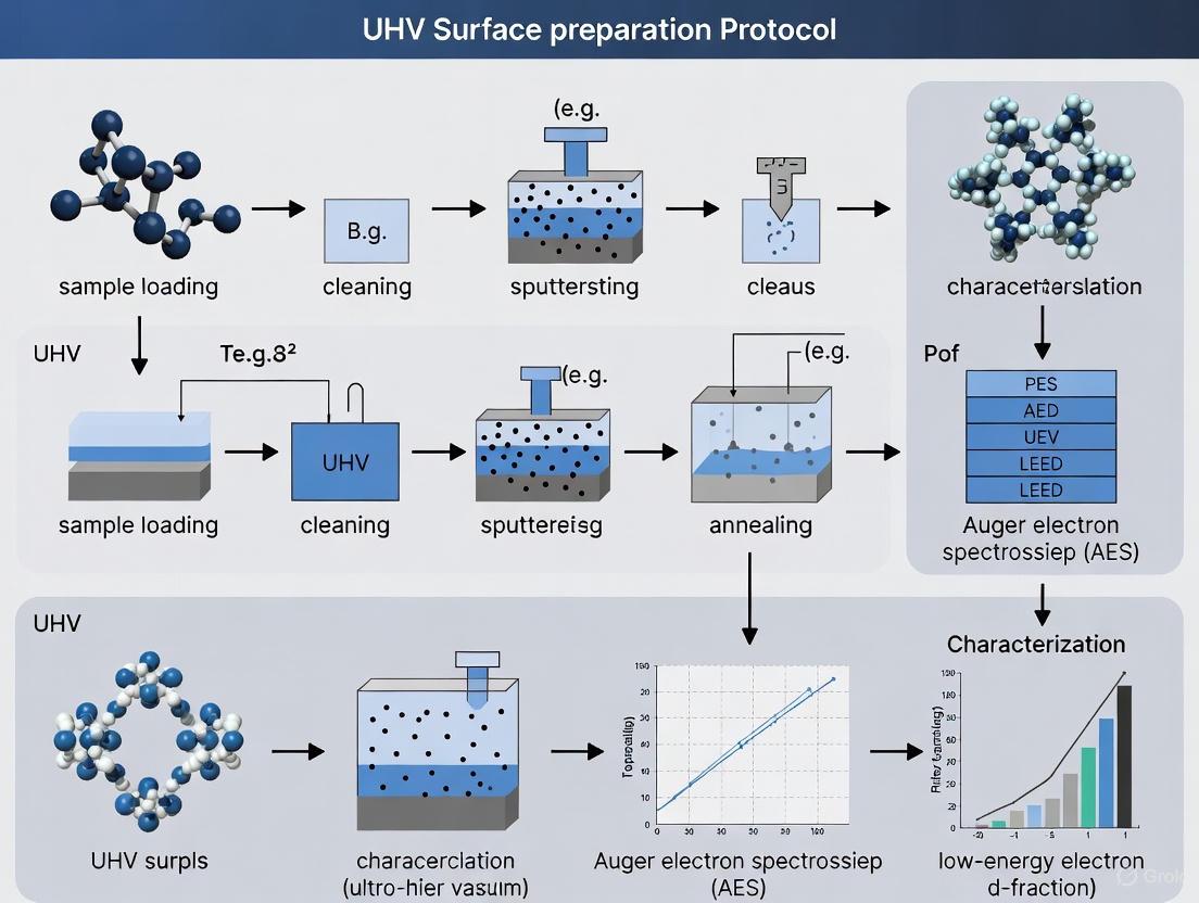
UHV System Protocol: Chamber Preparation and Bake-Out
A critical protocol for achieving UHV is the proper preparation and bake-out of the vacuum chamber. The following workflow outlines the essential steps:
The bake-out process involves heating the entire UHV system to temperatures between 200°C and 400°C for 24-48 hours while the vacuum pumps are running [1]. This thermal treatment dramatically accelerates the desorption of water vapor and hydrocarbons that have adsorbed on the chamber walls. Without baking, these contaminants would desorb slowly at room temperature, potentially preventing the system from ever reaching UHV conditions or requiring months to do so [3]. After baking, the dominant residual gases in a UHV system shift from water vapor to hydrogen and carbon monoxide, which originate from the diffusion of hydrogen from the stainless steel chamber walls [1].
Material Selection for UHV Compatibility
Material compatibility is crucial for UHV systems, as common materials can become significant gas sources through outgassing. The following table details essential materials and their functions in UHV applications:
Table 4: UHV-Compatible Materials and Research Reagents
| Material/Component | Function in UHV System | Key Properties | Common Examples |
|---|---|---|---|
| Austenitic Stainless Steel | Chamber construction, tubing, flanges | Low vapor pressure, low magnetic permeability, forms protective oxide layer | 304, 304L, 316, 316LN grades [1] |
| Oxygen-Free High-Conductivity Copper | Gaskets, electrical feedthroughs | High purity, minimal hydrogen content, deformable for sealing | OFHC copper for gaskets in ConFlat flanges [1] [5] |
| Ceramics (Alumina, Macor) | Electrical and thermal insulation | High electrical resistivity, low outgassing, machinable | Al₂O₃ for electrical feedthroughs [1] |
| Fluoropolymers | Limited use for specific applications | Extremely low outgassing (when properly baked) | PTFE, PEEK in minimal quantities [1] [3] |
| Metal Seals | Demountable vacuum connections | Plastic deformation creates hermetic barrier | Copper gaskets for ConFlat flanges [1] [3] |
Materials to avoid in UHV systems include most plastics (except specialized UHV-compatible grades), organic compounds, standard carbon steel, and high-vapor-pressure metals like zinc and cadmium [1]. These materials either outgas significantly or have high vapor pressures that prevent the attainment of UHV.
Advanced UHV Experimental Protocol: Surface Defect Characterization
UHV-FT-IR Protocol for Catalyst Surface Analysis
Fourier Transform Infrared (FT-IR) spectroscopy under UHV conditions provides powerful capabilities for characterizing catalytic surfaces. The following protocol, adapted from research on titanium dioxide (TiO₂) surfaces, demonstrates how UHV enables precise quantification of surface defects [7]:
Step 1: Sample Preparation
- Single crystal or powder samples are mounted on UHV-compatible holders.
- For powder samples (e.g., TiO₂ nanoparticles), press the powder against a gold-coated stainless steel grid (0.5 cm × 0.5 cm) to ensure mechanical stability and thermal contact [7].
Step 2: UHV Transfer and Surface Preparation
- Transfer the sample into the UHV system via a load-lock chamber to maintain the main chamber's UHV conditions.
- Clean single crystal surfaces (e.g., r-TiO₂(110)) using multiple cycles of Ar⁺ ion sputtering followed by annealing at 800 K in oxygen atmosphere [7].
- For powder samples, heat at 700 K in UHV to remove contaminants such as water and hydroxyl groups [7].
Step 3: Surface Defect Engineering
- Create a "perfect" (low-defect) surface by exposing the sample to a small amount of oxygen in UHV at 110 K [7].
- Generate oxygen vacancies through controlled sputtering or annealing at elevated temperatures (900 K) [7].
Step 4: CO Probe Molecule Dosing
- Cool the sample to 110 K to enhance CO adsorption.
- Expose the surface to carbon monoxide (CO) at controlled doses.
- CO molecules bind preferentially to specific Ti sites, with distinct vibrational frequencies indicating their proximity to oxygen vacancies [7].
Step 5: FT-IR Spectroscopy Measurement
- Acquire IR spectra using a vacuum FT-IR spectrometer with optical path evacuated to avoid atmospheric interference.
- For single crystals, use Infrared Reflection Absorption Spectroscopy (IRRAS) at grazing incidence (80° to surface normal) [7].
- For powder samples, use transmission geometry [7].
- Collect 1024 scans at 4 cm⁻¹ resolution for adequate signal-to-noise ratio [7].
Step 6: Defect Density Calculation
- Identify absorption bands in the CO-stretching region (approximately 2170-2190 cm⁻¹).
- The band at ~2188 cm⁻¹ corresponds to CO on regular Ti sites, while the band at ~2178 cm⁻¹ indicates CO adjacent to oxygen vacancies [7].
- Calculate oxygen vacancy concentration from the intensity ratio of these bands, considering maximum CO coverage (0.5 monolayer at 110 K) [7].
This protocol enables quantification of defect densities with remarkable precision (approximately 8-10% for reduced TiO₂ surfaces), demonstrating the critical role of UHV in establishing the relationship between surface defects and catalytic activity [7].
The UHV regime, defined by pressures below 10⁻⁷ mbar, creates unique environmental conditions essential for modern surface science. The exceptionally long mean free paths and dramatically reduced molecular fluxes in UHV enable both the preservation of atomically clean surfaces and the application of electron- and ion-based analytical techniques that would be impossible at higher pressures. Successful implementation of UHV technology requires meticulous attention to system design, material selection, and specialized protocols such as bake-out procedures. As demonstrated in the UHV-FT-IR protocol for catalyst characterization, the controlled environment of UHV systems provides unprecedented insights into surface structure and reactivity, forming the foundation for advancements in materials science, catalysis, and semiconductor technology. The continued refinement of UHV preparation protocols and analytical methods promises to further expand our understanding of surface phenomena at the molecular level.
In the realm of ultra-high vacuum (UHV) surface preparation protocol research, outgassing presents a fundamental challenge that directly impacts experimental integrity and system performance. Outgassing is the process whereby gases previously trapped, dissolved, or absorbed within materials are released upon exposure to vacuum conditions [8] [9]. This phenomenon occurs through several physical mechanisms including desorption, diffusion, permeation, and vaporization [10]. In UHV environments, defined as operating between 10⁻⁷ and 10⁻¹² mbar [11], outgassing becomes the dominant gas load, potentially contributing up to 100% of the total gas load in a leak-tight system [10].
The criticality of managing outgassing stems from its potential to compromise UHV processes through multiple pathways. Released volatiles can contaminate pristine surfaces, interfere with sensitive instrumentation, and elevate system pressure beyond operational thresholds [8] [9]. For researchers in surface science and drug development, uncontrolled outgassing can lead to unreliable experimental results, compromised sample purity, and reduced equipment lifespan. Understanding the sources, impacts, and control strategies for outgassing is therefore not merely a technical consideration but a foundational requirement for rigorous UHV research.
Fundamental Outgassing Mechanisms
Outgassing in UHV systems proceeds through four primary physical mechanisms, each with distinct characteristics and implications for system design:
- Desorption: The release of gas molecules bound to material surfaces, typically driven by thermal, electric, or photonic stimulation [8] [10]. This mechanism predominantly affects surface-adsorbed species such as water vapor, which constitutes 75-95% of the gas load at 10⁻³ mbar [10].
- Diffusion: The migration of gaseous molecules from a material's interior structure to its surface, driven by concentration gradients [8] [12]. This process is temperature-dependent and can persist long after initial pump-down.
- Permeation: The movement of gas molecules from the external atmosphere through the bulk material to the vacuum interior [8] [10]. This mechanism becomes particularly significant in Extreme High Vacuum (XHV) conditions below 10⁻¹² mbar [11].
- Vaporization: The release of molecules directly from the material surface itself [8] [10]. While negligible for most metals at typical operating temperatures, vaporization can be significant for polymers and composite materials.
Material-Specific Outgassing Rates
The propensity of materials to outgas varies dramatically across material classes. The following table summarizes typical outgassing rates for common engineering materials after one hour of pumping, illustrating the significant advantages of proper material selection:
Table 1: Typical Outgassing Rates for Common Engineering Materials [10]
| Material | Average Outgassing Rate (mbar·L·s⁻¹·cm⁻²) |
|---|---|
| Titanium | 1.0 × 10⁻⁸ |
| Pyrex | 9.9 × 10⁻⁹ |
| Copper | 2.3 × 10⁻⁸ |
| Stainless Steel | 1.9 × 10⁻⁷ |
| Aluminum | 3.0 × 10⁻⁷ |
| Viton A | 1.1 × 10⁻⁶ |
| PTFE | 1.4 × 10⁻⁶ |
| PVC | 3.2 × 10⁻⁶ |
| Neoprene | 4.0 × 10⁻⁵ |
These quantitative differences highlight why metals and glasses are preferred in UHV applications, while elastomers and plastics require careful consideration and treatment. For instance, stainless steel—a common UHV chamber material—has an outgassing rate nearly three orders of magnitude lower than Viton A, a frequently used elastomer [10].
Impacts of Outgassing on UHV Surface Research
Contamination and Surface Effects
In UHV surface preparation protocols, the primary concern with outgassing is molecular contamination of carefully prepared surfaces. Released volatiles can condense on critical surfaces, forming monolayers that alter surface chemistry and interfere with experimental results [8] [9]. For drug development research involving surface characterization techniques, even sub-monolayer contamination can significantly impact binding studies and surface interaction analyses.
The composition of outgassed species evolves with vacuum level. While water vapor dominates at higher vacuum pressures (10⁻³ mbar), hydrogen and carbon monoxide become predominant in UHV conditions (below 10⁻⁹ mbar) [10]. This shifting composition presents distinct challenges for different research applications, requiring tailored mitigation strategies.
System Performance Degradation
Beyond direct surface contamination, outgassing imposes significant operational constraints on UHV systems:
- Pressure Limitations: Outgassing establishes the ultimate base pressure achievable in a system, potentially limiting the vacuum quality essential for sensitive experiments [13].
- Pump-down Time Extension: The additional gas load from outgassing materials prolongs the time required to reach operational vacuum levels, reducing research throughput [14].
- Pumping Capacity Requirements: Systems with high outgassing materials require increased pumping capacity to maintain target pressures, elevating capital and operational costs [15].
Table 2: Dominant Gas Species by Pressure Range [10]
| Pressure (mbar) | Major Gas Load Composition |
|---|---|
| 10⁻³ | Water vapour (75-95%), N₂, O₂ |
| 10⁻⁶ | H₂O, CO, CO₂, N₂ |
| 10⁻⁹ | CO, H₂, CO₂, H₂O |
| 10⁻¹⁰ | H₂, CO |
| 10⁻¹¹ | H₂ |
Quantitative Assessment and Measurement Protocols
Standardized Testing Methods
Quantitative assessment of outgassing is essential for material selection and process validation in UHV research. The most widely recognized standard for evaluating outgassing is ASTM E595-07, which specifies testing at 125°C under a pressure of 10⁻⁶ Torr for 24 hours [9] [16]. This test measures two critical parameters:
- Total Mass Loss (TML): The percentage of original mass lost during testing, with NASA typically requiring <1.0% for space applications [9].
- Collected Volatile Condensable Materials (CVCM): The percentage of original mass that recondenses on nearby surfaces, with limits <0.1% for critical applications [9] [16].
Additional parameters sometimes measured include Water Vapor Regained (WVR) and Recovered Mass Loss (RML) [9]. For UHV applications, these standardized tests provide comparable data for informed material selection.
Direct Outgassing Rate Measurement
For research-grade validation, direct measurement of outgassing rates provides essential data for system design. The outgassing rate is expressed as the quantity of gas (pressure × volume) per unit surface area per unit time, with common units being Torr·L·s⁻¹·cm⁻² or mbar·L·s⁻¹·cm⁻² [13].
Two principal methods are employed for direct outgassing rate measurement:
- Rate-of-Rise Method: The chamber is evacuated, isolated from pumps, and the pressure increase over time (dP/dt) is measured. The outgassing rate is then calculated as ( \frac{V}{A} \times \frac{dP}{dt} ), where V is volume and A is surface area [13].
- Conductance Method: A pump remains connected to the vessel but is separated by a known conductance C. Measuring the pressure difference across this conductance allows calculation of the outgassing rate [13].
The conductance method generally provides faster measurements but requires accurate characterization of the conductance value [13]. Both methods are susceptible to measurement errors from gauge calibration, especially when using ionization gauges that can themselves outgas or act as pumps under certain conditions [13].
Diagram 1: Outgassing rate measurement workflow (76 characters)
Control Strategies and Mitigation Protocols
Material Selection and Surface Treatments
The most fundamental strategy for outgassing control begins with appropriate material selection and surface preparation:
- Material Choice: Prefer metals (stainless steel, titanium, copper) and ceramics over polymers and elastomers [10]. When polymers are unavoidable, select low-outgassing formulations specifically designed for UHV applications [9].
- Surface Polishing: Electropolishing stainless steel can reduce outgassing by a factor of 30, while mechanical polishing provides a factor of 50 reduction compared to untreated surfaces [17].
- Passivation Coatings: Apply barrier coatings via Chemical Vapor Deposition (CVD), Physical Vapor Deposition (PVD), or sputter coating at elevated temperatures (200-500°C) to create barriers against contaminant adsorption and permeation [17]. Non-Evaporable Getter (NEG) coatings can actively pump gases (H₂, CO, H₂O, O₂, N₂) but require periodic thermal activation [17].
Table 3: Effectiveness of Surface Treatments on Stainless Steel [17]
| Treatment Method | Reduction Factor | Application Notes |
|---|---|---|
| Electropolishing | 30× | Replaces amorphous surface layer with ordered oxide layer |
| Mechanical Polishing | 50× | Effective first treatment for gross contaminant removal |
| Bakeout (250°C for 30 hours) | >70,000× | Most effective for water vapor and hydrogen removal |
Baking and Thermal Processing Protocols
Thermal processing represents the most effective method for reducing outgassing in UHV systems:
- Low-Temperature Baking (100-250°C): Effectively removes water vapor and other weakly-bound surface species [17]. Typical protocols involve gradual temperature ramping (1-5°C/minute) with sustained baking for 24-48 hours under vacuum.
- High-Temperature Baking (250-1000°C): Required for hydrogen removal from the material bulk [17]. These aggressive protocols are typically applied during initial chamber preparation rather than routine maintenance.
- Vacuum Pre-baking of Components: Individually baking components before assembly prevents contamination of the main chamber. For electronic components like PCBs, IPC-1601 specifies baking at 100-125°C to remove moisture before soldering [12] [16].
The duration and temperature of baking protocols involve trade-offs between outgassing reduction and practical constraints. Longer and repeated baking cycles yield progressively lower outgassing rates, with demonstrable improvements even after hundreds of hours of cumulative baking [17].
Cleaning and Handling Procedures
Meticulous cleaning and handling procedures are essential for maintaining low-outgassing surfaces:
- Sequential Cleaning Protocol:
- Clean Handling Practices: Use powder-free latex gloves to prevent fingerprint contamination, which can take several days to desorb [17] [11]. Limit exposure to atmospheric moisture during assembly.
- System Venting Practices: When venting to atmosphere, use dry nitrogen rather than air to minimize water vapor adsorption [17]. Purging with dry gas can significantly reduce subsequent pump-down times.
Diagram 2: Systematic approach to outgassing control (76 characters)
The UHV Researcher's Toolkit
Essential Materials and Reagents
Successful UHV surface preparation requires carefully selected materials with documented low-outgassing characteristics:
Table 4: Essential Research Materials for UHV Applications
| Material/Component | Function | UHV-Specific Considerations |
|---|---|---|
| Stainless Steel (316L) | Chamber construction, fixtures | Low iron content, electropolished finish |
| Copper Gaskets | Static sealing for CF flanges | Single-use, proper torque application |
| OFHC Copper | Thermal transfer components | High purity minimizes outgassing |
| Titanium | Critical components | Excellent UHV compatibility, low hydrogen permeation |
| Pyrex/Borosilicate Glass | Viewports, electrical feedthroughs | Fire-polished edges reduce outgassing |
| Low-Outgassing Epoxies | Component bonding | Formulated to meet ASTM E595 requirements |
| Non-Evaporable Getter (NEG) | Active surface pumping | Requires thermal activation, pumps H₂, CO, CO₂ |
Specialized Equipment for Outgassing Management
Beyond standard UHV equipment, several specialized tools enhance outgassing control:
- Helium Leak Detector (HLD): Essential for detecting leaks as small as 10⁻¹² mbar·L·s⁻¹, distinguishing between true leaks and outgassing [11].
- Residual Gas Analyzer (RGA): Mass spectrometer for identifying specific outgassing species and quantifying their partial pressures [13].
- High-Temperature Bakeout Ovens: Capable of sustained operation up to 500°C for component preparation before UHV installation [17].
- Quartz Crystal Microbalance (QCM): Measures molecular contamination rates in real-time by detecting mass changes on a vibrating crystal [9].
- Electropolishing Setup: For creating smooth, low-outgassing surface finishes on metallic components [17].
Outgassing remains a critical challenge in UHV surface preparation protocols, directly impacting the integrity of scientific research across surface science, materials engineering, and drug development. Through systematic implementation of the control strategies outlined in these application notes—including rigorous material selection, comprehensive surface treatments, optimized baking protocols, and meticulous cleaning procedures—researchers can achieve the stable, clean vacuum environments essential for reliable surface studies.
The quantitative assessment methods and standardized protocols detailed herein provide a foundation for developing robust UHV research capabilities. As UHV technology advances toward ever-lower pressure regimes, continued attention to outgassing fundamentals will remain essential for pushing the boundaries of surface-sensitive research and development.
Ultra-high vacuum (UHV) systems, operating at pressures below 10⁻⁹ mbar, are critical for a wide range of scientific and industrial applications where molecular-level contamination must be eliminated [18] [19]. These environments are essential for processes such as semiconductor manufacturing, surface science research, and particle accelerator operations, where even monolayer formation can compromise results [18]. The selection of appropriate construction materials represents a fundamental consideration in UHV design, directly impacting base pressure attainment, contamination control, operational efficiency, and long-term system reliability. This application note provides a detailed comparative analysis of three principal materials—stainless steel, aluminum, and silicon—within the context of UHV surface preparation protocols. We examine their intrinsic material properties, performance characteristics in vacuum environments, and provide standardized preparation methodologies to achieve UHV-compatible surfaces, specifically framed for research applications in drug development and surface science.
Comparative Material Analysis
The selection of materials for UHV components involves balancing physical properties, chemical characteristics, and practical fabrication considerations. Table 1 provides a quantitative comparison of key properties for stainless steel, aluminum, and silicon relevant to UHV performance.
Table 1: Quantitative Comparison of UHV Material Properties
| Property | Stainless Steel (304/316) | Aluminum (6061) | Silicon |
|---|---|---|---|
| Outgassing Rate (after treatment) | Low (Requires bake-out) | Very Low (With proper treatment) | Extremely Low |
| Thermal Conductivity (W/m·K) | 15 - 20 | 150 - 200 | 130 - 150 |
| Coefficient of Thermal Expansion (10⁻⁶/K) | 16 - 18 | 23 - 24 | 2.6 |
| Machinability | Moderate (Cost: 5.5x aluminum) [18] | Excellent | Poor (Brittle) |
| Magnetic Permeability | Varies (316L is low) | Non-Magnetic | Non-Magnetic |
| Primary UHV Application | General chambers, beamlines, flanges | Cluster tools, cryogenic shields, structural frames | Specialist components, wafer substrates |
Material-Specific Advantages and Limitations
Stainless Steel (304/316L): This is a traditional choice for UHV chambers and components. Its primary advantage lies in its well-understood fabrication and welding techniques. However, it is a "notorious water sponge," requiring prolonged bake-out cycles at temperatures of 150-250°C to desorb water vapor and achieve ultimate pressure [18]. Furthermore, its low thermal conductivity can be a limitation for applications requiring rapid thermal cycling or efficient heat dissipation. Concerns also exist regarding potential iron and chromium contamination in sensitive processes [18].
Aluminum (e.g., 6061, 6063): Aluminum offers superior thermal conductivity, which facilitates faster pump-down and bake-out cycles compared to stainless steel [18]. Its natural non-magnetic property is advantageous for applications involving magnetic fields. A key benefit is its excellent machinability, allowing for the creation of complex, compact components from a single plate, saving valuable cleanroom space [18] [20]. The main challenge historically has been achieving a UHV-compatible surface, as-machined or extruded surfaces have a porous, contaminated oxide layer that must be removed and reformed [18].
Silicon: While not a common structural material, silicon is the primary substrate in many semiconductor processing tools integrated into UHV systems. Its ultra-low outgassing and minimal contaminating potential are major benefits [20]. Its extreme brittleness and poor machinability limit its use to specific roles, such as viewport windows for infrared applications or specialized sample holders [21].
Surface Preparation Protocols for UHV Compatibility
Achieving UHV conditions requires not only selecting the right material but also applying rigorous surface treatments to minimize outgassing and vapor pressure. The following protocols outline standardized methodologies for each material.
Aluminum Surface Treatment Protocol
The native oxide layer on aluminum is porous and contaminated, requiring complete removal and reformation [18].
- Initial Degreasing: Clean components with a detergent in an ultrasonic bath or with modified alcohols to remove organic contaminants like grease and fingerprints [22].
- Alkaline Cleaning: Immerse the component in an alkaline solution (e.g., 5-10% NaOH) at 50-70°C for 5-15 minutes. This strips the existing, thick aluminum oxide layer and surface impurities [18].
- Rinsing: Immediately after alkaline cleaning, rinse thoroughly with deionized water to remove all traces of the cleaning agent.
- Oxide Reformation: Allow the clean, exposed aluminum surface to form a new native oxide in a clean, dry air environment. This newly formed oxide layer will be thin, dense, and non-porous, rendering the surface UHV-compatible [18].
- Drying: Use forced clean, dry air or nitrogen to ensure the component is completely dry before assembly. Trapped water is a significant source of vacuum contamination [22].
Stainless Steel Surface Treatment Protocol
The goal for stainless steel is to remove contaminants and passivate the surface to reduce its tendency to absorb water.
- Solvent Cleaning: Use non-aqueous solvents like modified alcohols to dissolve and remove organic contaminants and machining oils from the surface [22].
- Electropolishing (Recommended): This process removes a surface layer (e.g., 150 µm), eliminating the subsurface layer damaged by machining which contains voids, dislocations, and impurities. This results in a smooth, flawless surface with low effective surface area and minimal residual stress, drastically reducing outgassing [22].
- Passivation: Treat the surface with acids (e.g., nitric acid) to remove free iron particles and form a stable, protective chromium-rich oxide layer that enhances corrosion resistance.
- Final Rinsing and Drying: Rinse extensively with high-purity water, preferably deionized and filtered. Dry with clean, dry nitrogen or air [22].
- UHV Bake-Out: As a final step in situ, bake the entire assembled system under vacuum to 150-250°C for 24-48 hours to desorb the primary contaminant: water vapor [18].
Silicon Surface Treatment Protocol
Silicon preparation focuses on achieving extreme chemical cleanliness and surface perfection.
- RCA Standard Clean: This is a classic two-step cleaning procedure for silicon wafers.
- SC-1 (Standard Clean 1): A mixture of ammonium hydroxide, hydrogen peroxide, and water (typically 1:1:5) at 70-80°C. This removes organic contaminants.
- SC-2 (Standard Clean 2): A mixture of hydrochloric acid, hydrogen peroxide, and water (typically 1:1:6) at 70-80°C. This removes ionic and metallic contaminants.
- HF Dip: A brief immersion in a diluted hydrofluoric (HF) acid solution to strip the native silicon oxide layer, leaving a hydrogen-terminated, hydrophobic surface.
- Rinsing and Drying: Rinse with ultra-pure deionized water and use a spin-rinse dryer or Marangoni drying to prevent watermarks or particle deposition.
The following workflow diagram illustrates the decision-making process for selecting and preparing these materials for a UHV system.
Implementation in Research Systems
The Scientist's Toolkit: Essential UHV Materials and Reagents
Successful UHV surface preparation requires the use of specific, high-purity reagents and materials. Table 2 lists key items and their functions in the protocols described.
Table 2: Research Reagent Solutions for UHV Surface Preparation
| Reagent / Material | Function in UHV Preparation | Application Notes |
|---|---|---|
| High-Purity Alkaline Solutions | Strips porous native oxide from aluminum to allow a dense, new oxide to form. | Critical for creating UHV-compatible aluminum surfaces [18]. |
| Modified Alcohol Solvents | Dilutes and removes organic contaminants (oils, greases) without severe toxicity. | Preferred over aggressive solvents for initial degreasing [22]. |
| Electropolishing Electrolytes | Removes subsurface damage layer and smoothens surface, drastically reducing outgassing. | Standard for stainless steel; creates a flawless surface finish [22]. |
| RCA Clean Chemicals (NH₄OH, H₂O₂, HCl) | Removes organic, ionic, and metallic contaminants from silicon surfaces. | Industry-standard for silicon wafer cleaning. |
| Hydrofluoric Acid (HF) | Strips native oxide from silicon, leaving a hydrogen-terminated surface. | Requires extreme caution and specialized equipment for handling. |
| High-Purity Aluminum Foil | Used for storing and transporting prepared samples; provides a clean barrier. | Alternative to plastic containers which can be sources of contamination [23]. |
| Polyethylene Gloves | Handles samples and components without introducing silicone contamination. | Other gloves contain silicones that are common surface contaminants [23]. |
Ancillary Component Integration
UHV systems incorporate various components whose material selection is equally critical. Motorized positioning stages used within the vacuum must be constructed from materials like stainless steel, aluminum, or titanium, with special attention to avoiding conventional lubricants that outgas hydrocarbons [19]. Similarly, viewports require careful material pairing; for example, fused silica is used for UV laser applications, sapphire for broad transmission from UV to near-IR, and zinc selenide for IR and thermal imaging [21]. Conductive coatings such as Indium Tin Oxide (ITO) can be applied to viewports to prevent electrostatic charging [21].
The selection between stainless steel, aluminum, and silicon for a UHV system is a strategic decision guided by application-specific requirements. Stainless steel offers proven reliability for general chambers but imposes operational penalties due to its high water retention and need for prolonged baking. Aluminum presents a high-performance alternative with superior thermal management and machinability, provided its surface is correctly treated to form a UHV-compatible oxide layer. Silicon, while not a structural material, is unmatched for its purity in substrate and specialist optic applications. The standardized surface preparation protocols detailed in this note—electropolishing and passivation for stainless steel, alkaline cleaning and oxide reformation for aluminum, and the RCA clean for silicon—are foundational to achieving the requisite surface purity for UHV operation. By adhering to these material selection principles and preparation protocols, researchers and engineers can design and maintain UHV systems that meet the stringent contamination-control standards required for advanced research in drug development, semiconductor processing, and surface science.
Surface oxide layers present a fundamental duality in ultra-high vacuum (UHV) surface science and materials engineering. These naturally occurring or synthetically grown films serve as essential protective barriers against corrosion and degradation while simultaneously functioning as potential traps for chemical contaminants that compromise surface purity and experimental integrity. Within the context of UHV surface preparation protocol research, this dual nature necessitates carefully balanced experimental approaches that either exploit the protective qualities of oxide layers or strive for their complete removal and replacement with controlled, pristine films. The strategic management of surface oxides becomes particularly critical for research involving catalytic surfaces, electronic device fabrication, and fundamental surface science studies where even monolayer contamination can dramatically alter experimental outcomes. This application note details protocols for controlling surface oxide layers, providing researchers with methodologies to either preserve their protective function or eliminate their contaminant-trapping potential for UHV-based investigations.
The Dual Nature of Surface Oxides: Protection Versus Contamination
Surface Oxides as Protective Barriers
Surface oxide layers function as protective barriers through several mechanisms that inhibit degradation of the underlying material. In metallic biomaterials such as titanium and its alloys, a thin, retentive oxide film protects the underlying metal from corrosion, preventing the release of toxic metal particles that could evoke adverse biological reactions [24]. This protective function is crucial for implant longevity, as corrosion products can lead to osteolysis and eventual implant failure [24].
In photoelectrochemical (PEC) systems, atomic layer deposition (ALD) of protective oxide layers such as TiO₂ significantly enhances electrode stability by preventing chemical/electrolyte/photo-corrosion of base materials like Cu₂O [25]. These protection layers reduce charge recombination at the electrode-electrolyte interface, thereby enhancing PEC reaction kinetics. The protective efficacy depends critically on layer thickness, with studies indicating that >30-nm-thick TiO₂ films provide stable performance, although excessive thickness can detrimentally impact light absorption capabilities [25].
Table 1: Protective Oxide Layers in Different Applications
| Material System | Protective Oxide | Protective Mechanism | Optimal Thickness |
|---|---|---|---|
| Ti6Al4V Implants | Native TiO₂ | Corrosion barrier preventing metal ion release | 2-10 nm (native) |
| Cu₂O Photoelectrodes | ALD TiO₂ | Prevention of photo-corrosion | ~20 nm |
| Hematite Photoanodes | ALD Al₂O₃ | Decreased carrier recombination | ~4 nm |
| AZO Conductive Films | ALD TiO₂ | Prevention of electrolyte penetration | ~10 nm |
Surface Oxides as Contamination Traps
Despite their protective benefits, surface oxides readily function as contamination traps through various mechanisms. The highly porous nature of certain anodic oxides, such as those created through micro-arc oxidation (MAO), creates abundant sites for contaminant adsorption and entrapment [26]. In UHV surface studies of materials like MoS₂, surface oxides and residual contaminants present significant analytical challenges, with carbonaceous contamination persisting even under UHV conditions [27].
The semiconductor industry faces particular challenges with oxide-related contamination, where fixed contamination forms strong electrostatic or chemical bonds with surface oxides [28]. This fixed contamination differs from smearable contamination, which can be removed by simple wiping, whereas fixed contamination typically requires harsh removal techniques such as chemical dissolution or scabbling [28]. The effectiveness of decontamination processes is quantified by the decontamination factor (DF), calculated as the ratio of contamination levels before and after decontamination [28].
Quantitative Analysis of Oxide Layer Properties
The protective and contaminant-trapping properties of surface oxides correlate directly with their physical and chemical characteristics. Systematic analysis of these parameters enables researchers to predict and control oxide behavior in UHV environments.
Table 2: Quantitative Characterization of Surface Oxide Layers
| Characterization Parameter | Analytical Technique | Significance for UHV Applications |
|---|---|---|
| Oxide Thickness | ESCA/XPS, Ellipsometry | Determines barrier effectiveness and electronic properties |
| Elemental Composition | ESCA, EDS, AES | Identifies doping elements and contaminant incorporation |
| Surface Roughness | AFM, Profilometry | Affects contaminant adhesion and surface area |
| Crystalline Structure | XRD, TEM | Influences chemical stability and electronic properties |
| Wettability/Contact Angle | Goniometry | Predicts interfacial interactions with contaminants |
| Surface Net Charge | AFM Force Measurement | Determines electrostatic contaminant attraction |
Research on Ti6Al4V alloys demonstrates that surface treatments significantly alter oxide properties. Radiofrequency plasma glow discharge (RFGD) treatment in oxygen increases oxide wettability and net positive surface charge at pH values below 6, while creating a higher net negative surface charge at physiological pH (7-8) compared to untreated controls [24]. Heat treatment to 600°C produces substantial topographic changes, creating nanostructured oxide elevations approximately 50-100 nm in diameter with a three-fold increase in roughness compared to untreated surfaces [24].
Experimental Protocols for Surface Oxide Control
Protocol 1: Atomic Layer Deposition of Protective Oxide Coatings
Principle: Atomic layer deposition enables conformal, pinhole-free oxide coatings with precise thickness control at the atomic scale, providing optimal protection for underlying materials while minimizing contaminant trapping sites.
Materials:
- Precursor Materials: Trimethylaluminum (TMA) for Al₂O₃, titanium tetrachloride (TiCl₄) or tetrakis(dimethylamido)titanium (TDMAT) for TiO₂
- Oxygen Source: H₂O, O₃, or O₂ plasma
- Inert Carrier Gas: High-purity N₂ or Ar
- Substrate: Pre-cleaned material (Si wafer, metal foil, or specialized substrates)
- ALD Reactor: Thermal or plasma-enhanced system with precise temperature and pressure control
Procedure:
- Substrate Preparation: Clean substrate using appropriate protocol (RCA cleaning for Si, electrochemical polishing for metals) to remove native contaminants.
- Reactor Loading: Transfer substrate to ALD reactor under controlled atmosphere to minimize air exposure.
- System Conditioning: Pump reactor to base pressure (<10⁻³ Torr) and stabilize at deposition temperature (100-300°C depending on material).
- ALD Cycling: a. Precursor Dose: Introduce metal precursor pulse (0.1-0.5 s) followed by purging with inert gas (10-30 s) b. Reactant Dose: Introduce oxygen source pulse (0.1-0.5 s) followed by purging (10-30 s) c. Cycle Repetition: Repeat sequence until desired thickness achieved (growth per cycle typically 0.5-1.5 Å)
- Post-deposition Annealing: Optional thermal treatment (300-500°C in O₂ or inert atmosphere) to improve crystallinity and stability.
Quality Control:
- Verify thickness using spectroscopic ellipsometry
- Confirm composition using XPS or AES
- Check for pinholes using electrochemical tests or SEM inspection
- Validate conformality using trench structures or high-aspect-ratio substrates
Protocol 2: Mechanical Exfoliation of Surface Oxides and Contaminants
Principle: Mechanical exfoliation provides a rapid method for removing surface oxides and contaminants from layered materials, producing atomically clean surfaces for UHV analysis.
Materials:
- Bulk crystalline material (MoS₂, HOPG, etc.)
- Exfoliation tapes: Regular acrylic, heat-resistant, or double-sided conductive tapes
- Substrates: SiO₂/Si wafers, gold-coated Cu-Be foils
- Optical microscope for sample inspection
- UHV transfer system
Procedure:
- Tape Selection: Choose appropriate exfoliation tape based on material properties and desired surface quality.
- Exfoliation Technique: a. Standard Method: Apply tape over entire sample surface and peel off slowly from one end b. Edge-initiated Method: Attach tape to one sample edge and peel parallel to sample plane c. Iterative Method: Repeatedly fold and peel tape to progressively thin material
- Surface Transfer: Press freshly-exposed material surface against clean substrate
- Tape Removal: Carefully peel back tape at 180° angle to leave thin flakes on substrate
- UHV Transfer: Immediately transfer exfoliated sample to UHV chamber (<1×10⁻⁹ Torr) to minimize contamination
Optimization Notes:
- Gold-coated Cu-Be foils provide optimal electrical contact for spectroscopic analysis
- Ambient condition control (humidity <30%) improves reproducibility
- Parallel peeling technique produces larger, cleaner terraces compared to perpendicular peeling
Protocol 3: UHV Surface Rejuvenation via Sputter-Annealing Cycles
Principle: Sequential noble gas ion sputtering and thermal annealing effectively remove surface oxides and contaminants while enabling controlled oxide regrowth under clean conditions.
Materials:
- UHV System: Base pressure <1×10⁻¹⁰ Torr with sputter gun and sample heating capability
- Sputter Gas: High-purity Ar⁺, Ne⁺, or Kr⁺ (99.999%)
- Sample Holder: Direct resistive heating or electron bombardment heating capability
- Surface Analysis: In-situ AES, XPS, or LEED for process monitoring
Procedure:
- Initial Characterization: Acquire reference survey spectra (AES/XPS) to determine initial surface composition.
- Sputter Parameters: a. Ion Energy: 0.5-3 keV (lower energies minimize surface damage) b. Ion Current: 1-20 μA/cm² (optimize for removal rate versus surface roughness) c. Incidence Angle: 45-70° (grazing angles enhance sputter yield) d. Duration: 10-60 minutes (until contaminant signals minimized)
- Thermal Annealing: a. Temperature Ramping: Gradual increase to target temperature (2-5°C/s) b. Annealing Conditions: 400-800°C for 5-30 minutes in UHV c. Controlled Oxidation: Optional exposure to high-purity O₂ (1×10⁻⁶ - 1×10⁻⁴ Torr) for controlled oxide growth
- Cycle Repetition: Typically 3-10 sputter-anneal cycles until desired surface quality achieved
Application-Specific Parameters:
- MoS₂: 1 keV Ar⁺, 450°C annealing [27]
- Ti Alloys: 2 keV Ar⁺, 600°C annealing [24]
- Si: 0.5-1 keV Ar⁺, 850°C flash annealing
Research Reagent Solutions for Surface Oxide Management
Table 3: Essential Research Reagents for Surface Oxide Control
| Reagent/Chemical | Function | Application Notes | Safety Considerations |
|---|---|---|---|
| Trimethylaluminum (TMA) | ALD precursor for Al₂O₃ | Moisture-sensitive; requires anhydrous handling | Pyrophoric; strict exclusion of air/water |
| Titanium tetrachloride (TiCl₄) | ALD precursor for TiO₂ | Corrosive; produces HCl byproduct | Moisture-sensitive; corrosive fumes |
| High-purity O₂ gas (99.999%) | Oxidation source | For controlled oxidation and plasma processes | Oxidizer; compatible with UHV systems |
| Ar⁺ sputter gas (99.999%) | Surface cleaning | Low damage at 0.5-1 keV; higher yields at 2-3 keV | Inert; high-pressure cylinder handling |
| AgNO₃ | Antimicrobial incorporation | 0.5 mM in MAO electrolytes for antibacterial properties | Oxidizer; toxic if ingested |
| ZnCl₂ | Antimicrobial incorporation | 5.0 mM in MAO electrolytes for sustained protection | Moisture-sensitive; corrosive |
| Calcium glycerophosphate | MAO electrolyte component | 100 mM with calcium acetate for porous oxides | Irritant; use with PPE |
| Nitric acid (40%) | Passivation treatment | ASTM-F86 protocol for Ti alloys [24] | Strong oxidizer; severe corrosion hazard |
Visualization of Surface Oxide Control Strategies
Surface Oxide Management Decision Workflow
The strategic management of surface oxide layers represents a critical capability in UHV surface science, requiring researchers to navigate the delicate balance between exploiting their protective functions and mitigating their contaminant-trapping potential. The protocols detailed in this application note provide methodologies for either preserving protective oxide layers or eliminating them entirely for pristine surface studies. As surface science advances toward increasingly sensitive measurements and applications in quantum materials and single-atom catalysis, the precise control of surface oxide properties will continue to grow in importance. Researchers must select the appropriate strategy based on their specific application requirements, whether prioritizing the corrosion resistance offered by engineered oxide layers or the atomic-level cleanliness achieved through aggressive oxide removal techniques.
Within the broader context of UHV surface preparation protocol research, the achievement of pristine vacuum conditions is a prerequisite for reliable experimental outcomes. Ultra-High Vacuum (UHV), defined as the pressure range between 10⁻⁷ and 10⁻¹² mbar, is characterized by an environment where the dominant gas load originates from the release of gases from the chamber walls and internal components themselves, a process known as outgassing [15] [11]. To reach and maintain such extreme vacuum levels, the system design must aggressively minimize all potential gas sources. This application note details the fundamental principles and protocols for designing an efficient UHV system, with a specific focus on minimizing internal surface area and eliminating trapped volumes, which are two of the most critical factors in mitigating outgassing and virtual leaks.
Core Design Principles for UHV Systems
The design of a UHV system must adhere to stringent principles that diverge significantly from those of low-vacuum or atmospheric pressure equipment. The following principles are paramount for minimizing the gas load and achieving stable UHV conditions.
Minimizing Internal Surface Area
The rate of outgassing is directly proportional to the available internal surface area of the vacuum chamber [15]. Adsorbed water vapor and other contaminants on these surfaces represent a significant and persistent gas source. Consequently, a primary design goal is to minimize the chamber's internal surface area without compromising its structural integrity or functional volume [15] [11]. This involves using simple, compact geometries and avoiding complex internal baffles or supports wherever possible.
Elimination of Trapped Volumes and Virtual Leaks
Trapped volumes, such as those found in blind tapped holes or unvented gaps between assembled components, act as reservoirs of gas that can only be pumped through very restricted pathways [29]. These are known as virtual leaks and can considerably delay the pump-down process or prevent the system from reaching its base pressure, as the gas in these pockets escapes very slowly [30]. Designs must ensure there are no internal gaps or trapped volumes [15] [11]. A common and critical example is the use of vented screws—screws with a hole drilled through their axis—in blind holes to allow trapped gas to escape directly into the chamber volume where it can be pumped away [29].
Material Selection and Surface Treatment
The choice of materials and their pre-treatment is a fundamental aspect of UHV design. Materials must exhibit low desorption/outgassing rates and be compatible with high-temperature bake-out procedures [15] [30].
- Preferred Materials: Stainless steel, aluminum, titanium, and ceramic (e.g., Al₂O₃) are standard [30] [29]. For electrical insulation, polymers such as PEEK (Polyether Ether Ketone), PTFE (Teflon), and Polyimide (Kapton) are used instead of common plastics, which have high outgassing rates [30] [29].
- Surface Treatments: Electropolishing is the preferred surface treatment for UHV components as it creates a smooth, passivated surface that minimizes surface area and outgassing [15] [29]. Anodizing, a common treatment for aluminum, is typically avoided because its porous structure dramatically increases the effective surface area and can introduce outgassing contaminants from dyes [30].
- Joining and Sealing: All internal welds should be performed from the inside to prevent creating external grooves that can trap contaminants [15] [11]. Furthermore, the number of seals and feedthroughs should be minimized, and metallic seals (e.g., copper gaskets with knife-edge flanges) should be employed instead of elastomer seals for their lower outgassing rates and bake-ability [15].
Table 1: UHV Material and Treatment Selection Guide
| Category | Recommended for UHV | Not Recommended for UHV | Rationale |
|---|---|---|---|
| Structural Metals | Stainless steel, Titanium, certain Aluminum alloys | Brass, Copper-Zinc alloys (CuZn), Cadmium plating | Low outgassing, low vapor pressure, bakeable [30] [29] |
| Electrical Insulators | PEEK, PTFE (Teflon), Polyimide (Kapton), Macor, Sapphire | Standard nylon, PVC, epoxy resins | Withstand bake-out temperatures, very low outgassing rates [30] [29] |
| Surface Treatment | Electropolishing, Blanc (bare) aluminum | Standard anodizing, painted coatings | Smooth, non-porous surface that minimizes area and outgassing [30] |
| Seals | All-Metal Seals (e.g., Copper C-rings) | Elastomer seals (Viton, Buna) | No organic outgassing, can withstand high bake-out temperatures (>150°C) [15] |
Experimental Protocols for UHV System Preparation
The following protocols are essential for preparing and maintaining a UHV system, ensuring that the careful design principles are not compromised during assembly and operation.
Protocol: UHV Component Cleaning and Assembly
This protocol outlines the procedure for preparing components prior to their installation into a UHV system.
3.1.1. Objective: To remove all particulates, chemical residues, and organic contaminants from UHV components without introducing new contaminants. 3.1.2. Materials & Reagents:
- Ultrasonic cleaning bath
- High-purity solvents (e.g., isopropyl alcohol, acetone)
- Climate-controlled drying cabinet or oven
- Class 100 cleanroom or laminar flow box
- Powder-free latex or nitrile gloves [11]
- Clean-room wipes
- Vacuum-compatible packaging materials
3.1.3. Methodology:
- Initial Degreasing: Wipe components with clean-room wipes and a high-purity solvent to remove gross contamination.
- Ultrasonic Cleaning: Submerge components in an ultrasonic bath filled with a suitable high-purity solvent. This is the initial and key step for removing adhered particles and contaminants [30] [29].
- Drying: Transfer the cleaned components to a climate cabinet and dry under a pure nitrogen atmosphere to prevent water condensation and re-contamination [30].
- Assembly: Assemble the stage or component in a cleanroom or laminar flow box by personnel wearing powder-free gloves to prevent fingerprint contamination [11] [30].
- Packaging and Shipping: Pack the assembled unit in vacuum-sealed bags to protect it from dirt, air, and humidity during transport or storage [30].
Protocol: System Bake-Out
3.2.1. Objective: To accelerate the desorption of water vapor and other volatiles from the vast internal surface area of the chamber and components. 3.2.2. Methodology:
- After rough pumping, uniformly heat the entire vacuum system using heating tapes or an oven.
- Typical bake-out temperatures range from 150°C to 250°C for periods of 24 to 48 hours [29]. Specific components, such as all-ceramic piezo actuators, can withstand bake-out temperatures of up to 150°C [29].
- Continue pumping during the bake-out cycle. The increased temperature dramatically increases the outgassing rate, allowing the pumps to remove the vast majority of the adsorbed gas.
- After the bake-out period, allow the system to cool while under vacuum. The resulting pressure will be orders of magnitude lower than before the bake-out.
The Scientist's Toolkit: Essential UHV Research Reagents and Materials
Table 2: Key Research Reagent Solutions for UHV Applications
| Item Name | Function / Application in UHV | Critical Consideration |
|---|---|---|
| PICMA Piezo Actuators | Provides nanometer-precision positioning inside the UHV chamber. Ideal for sample manipulation [29]. | All-ceramic construction eliminates outgassing from polymer insulation; bakeable to 150°C; operates in magnetic fields and cryogenic environments [29]. |
| Vacuum-Compatible Stepper Motors | Drives precision stages for larger travel ranges within the UHV environment [29]. | Features stainless steel housing, high-temperature stable components, and minimal use of organics; designed for pressures down to 10⁻⁹ hPa [29]. |
| Ultrasonic Cleaning Solvents | Used in the multi-stage cleaning process to remove particulate and hydrocarbon contamination from components before assembly [30] [29]. | Must be high-purity grade to prevent residue deposition. Isopropyl alcohol and acetone are common choices. |
| Helium Leak Detector (HLD) | The only credible method for detecting very small leaks (smaller than 10⁻⁷ mbar·l/s) in a UHV system [11]. | Uses helium as a tracer gas and a mass spectrometer for detection. Essential for locating leaks that would prevent the system from reaching base pressure. |
| Metallic Seals (e.g., Copper) | Provides a hermetic seal between UHV flanges (e.g., ConFlat). | Withstands high bake-out temperatures and provides an extreme leak-tight seal with very low outgassing, unlike polymer seals [15]. |
System Design and Pumping Strategy Workflow
The following diagram illustrates the logical workflow for designing and commissioning a UHV system, integrating the principles and protocols discussed above.
Step-by-Step UHV Preparation Protocols for Metals and Semiconductors
Achieving ultra-high vacuum (UHV) conditions is paramount in advanced research and industrial applications, including particle accelerators, synchrotron light sources, and semiconductor manufacturing. The performance and yield in these fields are critically dependent on molecular-level surface cleanliness, where base pressures at or below 10^-9 Torr are required to minimize environmental contamination [18]. Contaminants on vacuum chamber surfaces, such as oils, metallic smut, and porous oxide layers, act as significant sources of outgassing, compromising vacuum integrity and process purity. Consequently, meticulous chemical pre-treatment of chamber components, specifically through etching and de-smutting protocols, forms the foundational step in UHV surface preparation.
This document outlines standardized application notes and experimental protocols for the chemical pre-treatment of two key structural metals: aluminum and stainless steel. The procedures are framed within a broader UHV protocol research context, providing researchers and drug development professionals with validated methodologies to prepare metal surfaces that meet the exacting cleanliness standards required for sensitive vacuum environments. The focus is on reproducible, quantifiable processes that remove impurities and reform passive oxide layers into thin, dense, and non-porous barriers ideal for UHV service [31] [18].
Aluminum Pre-Treatment for UHV
Background and Principles
Aluminum alloys are widely used in UHV systems due to their excellent machinability, low cost, and favorable thermal properties [18]. However, the native oxide layer that forms on aluminum is typically thick (20-200 Å), porous, and contaminated with alloying elements from manufacturing processes [31] [18]. This layer can trap water vapor and other contaminants, leading to persistent outgassing. The goal of chemical pre-treatment is to strip this native oxide and allow a new, thin (angstrom-scale), dense, and non-porous oxide layer to form uniformly [32]. A key challenge is "smut"—finely divided residues of alloying elements like copper, silicon, or iron that remain on the surface after etching and must be removed [31] [33].
Established Protocols from National Laboratories
Research institutions leading in UHV technology have developed and refined several cleaning processes. The following table summarizes several documented procedures for cleaning aluminum alloys.
Table 1: Comparison of Aluminum Cleaning Processes for UHV Service
| Institution (Application) | Aluminum Alloys | Cleaning Method Sequence |
|---|---|---|
| Argonne National Laboratory (Advanced Photo Source) [31] | 6063 | 1. High-pressure spray with 2% Almeco 18.2. Ultrasonic clean with 2% Almeco 18 at 65°C for 10 min.3. Rinse with room-temperature DI water for 10 min.4. Blow dry with hot nitrogen. |
| Brookhaven National Laboratory (National Synchrotron Light Source) [31] | 6000 Series | 1. Ultrasonic clean with Almeco 18 at 77°C.2. DI water rinse at 60°C.3. Buff Out 16000 solution at 77°C.4. Rinse in DI water at 60°C.5. Citrinox solution at 77°C.6. DI water rinse at 60°C.7. Nondenatured ethanol rinse at 25°C.8. Blow dry with air at 25°C. |
| CERN [31] | 6061, 6063 | 1. High-pressure spray jet with Almeco 29 at 60°C.2. High-pressure spray jet with Amklene D Forte.3. Rinse with hot DI water spray jet.4. Dry in air at 80°C. |
| Meyer Tool & Mfg., Inc. (Based on Lawrence Livermore National Laboratory methods) [31] | 6000 & 5000 Series | 1. High-pressure spray with Brulin 1990 GD at 50°C, rinse with DI water.2. Repeat step 1.3. Dry with nitrogen/oil-free air.4. Immerse in 30% phosphoric acid for 30 min, then dry.5. Repeat step 1 twice, then dry. |
Detailed Step-by-Step Experimental Protocol: Alkaline Etch and Acid De-smut
The following is a detailed, bench-level protocol adapted from procedures used at JILA and CERN, which is suitable for smaller components that can be immersed in baths [32].
Figure 1: Aluminum UHV pretreatment workflow.
Step 1: Prepare the Etchant Bath
- Objective: Create a 5.5% (1.39 mol/L) sodium hydroxide (NaOH) solution for etching [32].
- Materials:
- Sodium hydroxide (NaOH) pellets.
- Deionized (DI) or tap water.
- A chemically resistant tank (e.g., stainless steel, polypropylene).
- Heating and stirring apparatus (e.g., hot plate).
- Fume hood.
- Procedure:
- Add 35 L of water to the tank.
- While wearing appropriate Personal Protective Equipment (PPE), slowly add 0.973 kg of NaOH pellets to the water while stirring. Note: This is an exothermic reaction; add slowly to control heat and splashing.
- Heat the solution to a target temperature of 70°C [32]. The solution may become clear as it heats and the NaOH fully dissolves.
Step 2: Alkaline Etch
- Objective: Strip the existing porous oxide layer and a small amount of underlying aluminum.
- Materials: Tongs or baskets resistant to strong bases.
- Procedure:
- Immerse the aluminum component in the heated NaOH bath for 60 seconds [32].
- Agitate gently to ensure uniform etching. A visible reaction with gas evolution should occur.
- Remove the component from the bath. The surface will appear dark or smutty due to residual alloying elements.
Step 3: Rinse (Tap Water)
- Objective: Rapidly terminate the etching reaction and remove residual NaOH.
- Procedure:
- Immediately and thoroughly rinse the component under a stream of tap water [32].
- Ensure all surfaces are thoroughly rinsed to prevent carryover of alkaline solution into the acid bath.
Step 4: Prepare the De-smut Bath
- Objective: Create a 25% nitric acid solution with ammonium bifluoride to remove the smut.
- Materials:
- Concentrated (70%) Nitric Acid (HNO₃).
- Ammonium bifluoride (NH₄HF₂).
- A secondary containment bin made of high-density polyethylene (HDPE) or polypropylene.
- Procedure:
- Add 12.5 L of water to the HDPE bin.
- Slowly and carefully add 5 Liters of 70% Nitric Acid to the water while stirring. Warning: This is a highly exothermic dilution. Pour slowly to avoid localized boiling and splashing. Monitor temperature to ensure it stays below 80°C to avoid damaging the HDPE container.
- Add 25g of ammonium bifluoride (0.1% concentration) to the acid solution [32]. The fluoride acts as a catalyst for the nitric acid's de-smutting action.
Step 5: Acid De-smut
- Objective: Dissolve the metallic smut residues, leaving a bright, clean aluminum surface.
- Procedure:
- Immerse the rinsed aluminum component in the de-smut bath for 5 minutes at room temperature (approx. 20°C) [32].
- The smut should dissolve, and the surface will become visually bright and clean.
Step 6: Rinse (DI Water)
- Objective: Remove all traces of acid and dissolved metallic ions from the surface.
- Procedure:
- Transfer the component to a bath of DI water. Do not leave immersed for more than 10-15 minutes to prevent the initiation of corrosion [32].
- A final rinse with hot DI water, if available, can aid in drying.
Step 7: Dry
- Objective: Remove all moisture without re-contaminating the surface.
- Materials: Filtered, oil-free compressed air or nitrogen.
- Procedure:
The Scientist's Toolkit: Key Reagents for Aluminum Pre-Treatment
Table 2: Essential Reagents for Aluminum UHV Pre-Treatment
| Reagent/Solution | Function | Application Note |
|---|---|---|
| Sodium Hydroxide (NaOH) | Strong alkaline etchant. Removes the native aluminum oxide layer and underlying aluminum. | Concentration and temperature must be controlled to prevent over-etching and excessive smut formation [32]. |
| Nitric Acid (HNO₃) | Oxidizing acid. Removes metallic "smut" (e.g., copper, silicon) left after alkaline etching and passivates the surface [33]. | Produces a thin, dense oxide layer. Often used in concentrations of 20-25% [32]. |
| Ammonium Bifluoride (NH₄HF₂) | Source of fluoride ions. Acts as an activator for nitric acid, enhancing its ability to dissolve certain types of smut [32]. | A small concentration (e.g., 0.1%) is typically sufficient. |
| Phosphoric Acid (H₃PO₄) | Mild oxidizer. Used in newer methods as an alternative to alkaline etching to minimize smut formation, followed by a detergent clean [31]. | Effective for high-particulate-cleanliness applications, as used for the National Ignition Facility [31]. |
| Citrinox | Citric acid-based cleaner. Effectively removes copper smut without the use of more hazardous acids [31]. | A safer, environmentally friendly alternative, suitable for alloys prone to smutting (e.g., 2219) [31]. |
| Almeco 18/29 | Commercial alkaline detergents. Used to remove oils and modify the oxide layer without aggressive etching [31]. | Often used in initial cleaning steps or for reforming the oxide layer on extruded aluminum [31]. |
Stainless Steel Pre-Treatment for UHV
Background and Principles
Ultra-high purity (UHP) 316L stainless steel is the material of choice for critical components in the semiconductor industry, such as electronic special gas (ESG) delivery pipelines [34]. While known for good corrosion resistance, its performance in UHV and corrosive ESG environments (involving HCl, HBr, HF, Cl₂) is critical. Trace moisture can condense and dissolve these gases, forming a highly aggressive acidic electrolyte that leads to corrosion. The resulting corrosion particles can detach and contaminate processing chambers, drastically reducing wafer yields [34]. Therefore, pre-treatment aims not only to clean but also to maximize the corrosion resistance of the passive film.
Advanced Passivation Protocol for UHP 316L Stainless Steel
The following protocol is based on recent research for a composite passivation strategy that combines Alternating Voltage Passivation (AVP) with Nitric Acid Passivation (NP) to achieve superior corrosion resistance without surface damage, making it ideal for semiconductor applications [34].
Figure 2: Stainless steel composite passivation workflow.
Step 1: Electropolishing (EP)
- Objective: Smooth the surface and create a baseline passive film with improved corrosion resistance.
- Procedure:
- Follow standard electropolishing procedures for 316L stainless steel. This typically involves immersing the part as an anode in a temperature-controlled acidic electrolyte (e.g., a mixture of sulfuric and phosphoric acids) and applying a specific current density.
- Rinse thoroughly with DI water after electropolishing. EP is recognized as an excellent technique for enhancing corrosion resistance and surface quality [34].
Step 2: Alternating Voltage Passivation (AVP)
- Objective: Dramatically enhance the thickness and stability of the passive film and selectively dissolve corrosive-inclusion weaknesses.
- Materials: Potentiostat, counter electrode, reference electrode, and electrolyte (e.g., 0.1 mol/L Na₂SO₄).
- Procedure:
Step 3: Nitric Acid Passivation (NP)
- Objective: Heal the micro-damage induced by AVP and further enrich the chromium content in the passive film, achieving a defect-free, highly protective surface.
- Procedure:
- Immerse the AVP-treated sample in a 20% nitric acid solution.
- Maintain the solution at 60°C for 60 minutes [34].
- This step eliminates surface micro-pitting and grain boundary etching caused by AVP.
Step 4: Rinse and Dry
- Objective: Remove all passivation chemicals.
- Procedure:
- Rinse the component thoroughly with DI water.
- Dry using filtered, oil-free air or nitrogen. The component now has a highly resistant, stable passive film suitable for UHV and corrosive ESG service.
The Scientist's Toolkit: Key Reagents & Materials for Stainless Steel Pre-Treatment
Table 3: Essential Reagents for Stainless Steel UHV Pre-Treatment
| Reagent/Solution | Function | Application Note |
|---|---|---|
| Electropolishing Electrolyte | Anodic dissolution. Levels micro-peaks, smooths the surface, and creates a uniform baseline passive film, improving corrosion resistance [34]. | Typically a mixture of sulfuric and phosphoric acids. Process parameters (temp, current density, time) are critical. |
| Sodium Sulfate (Na₂SO₄) Solution | Electrolyte for AVP. Provides the conductive medium for the alternating voltage treatment. | A 0.1 mol/L concentration is used as a non-aggressive medium to facilitate passive film growth [34]. |
| Nitric Acid (HNO₃) | Traditional passivating agent. Promotes the formation of a chromium-rich passive oxide layer by selectively dissolving iron from the surface. | Used at 20% concentration and elevated temperature (60°C) to heal AVP-induced surface damage and enhance film stability [34]. |
| Ultra-High Purity 316L Stainless Steel | Base material. Specially manufactured with strict limits on S, Mn, Al, C, and Ca to minimize the formation of corrosive inclusions [34]. | Complies with SEMI F20 standard. The reduced inclusion count is a prerequisite for the success of advanced passivation techniques. |
The pursuit of UHV conditions demands rigorous and repeatable metal pre-treatment protocols. For aluminum, this involves a two-stage process of alkaline etching to strip the porous native oxide, followed by acid de-smutting to remove residual metallic impurities, resulting in a clean, thin, and protective new oxide layer. For ultra-high purity stainless steel in the most demanding semiconductor applications, a composite passivation strategy combining the film-forming power of AVP with the surface-healing properties of nitric acid passivation offers a breakthrough in corrosion resistance without compromising surface quality. By adhering to these detailed application notes and protocols, researchers and engineers can reliably prepare metal surfaces that meet the extreme cleanliness and stability standards required for advanced UHV systems.
Plasma cleaning, utilizing the fourth state of matter, is a critical surface preparation technique in ultra-high vacuum (UHV) environments for research and industrial applications. This process employs an ionized gas containing reactive species to remove contaminants at the molecular level, achieving cleanliness standards unattainable through conventional methods [35]. Within the context of UHV surface preparation protocol research, the selection of specific plasma chemistry—hydrogen, oxygen, or argon—determines the mechanism and outcome of the cleaning process [35] [36]. This analysis provides a comparative examination of these three plasma techniques, detailing their fundamental mechanisms, specific applications across material classes, and standardized protocols for reproducible surface preparation in UHV systems.
Comparative Analysis of Plasma Types
The efficacy of plasma cleaning depends on selecting the appropriate process gas, which determines the dominant cleaning mechanism—chemical reaction, physical sputtering, or a combination of both. The table below summarizes the key characteristics of hydrogen, oxygen, and argon plasmas.
Table 1: Comparative Analysis of Hydrogen, Oxygen, and Argon Plasma Cleaning Techniques
| Parameter | Hydrogen Plasma | Oxygen Plasma | Argon Plasma |
|---|---|---|---|
| Primary Mechanism | Chemical reduction [35] [36] | Chemical oxidation [35] [37] | Physical sputtering [35] [38] |
| Chemical Reactivity | Highly reductive [35] | Highly oxidative [35] [37] | Inert (non-reactive) [37] |
| Key Reactive Species | H atoms, H⁺ ions, H₂⁺ ions [36] | O atoms, O₂⁺, O₂⁻, O₃ [37] [36] | Ar⁺ ions, metastable Ar atoms [37] |
| Primary Contaminant Removal | Native oxide layers [35] [36] | Organic residues (hydrocarbons) [35] [37] | Inorganics, salts, ceramics [36] |
| By-products | H₂O vapor [36] [38] | CO, CO₂, H₂O [35] [36] | Vaporized contaminants [35] |
| Effect on Surface Chemistry | Reduces metal oxides to pure metal; leaves H-terminated surfaces [35] [39] | Adds oxygen-containing polar groups (e.g., -OH, C=O); creates hydrophilic surface [37] | Creates surface radicals; post-air exposure introduces functional groups [37] |
| Effect on Surface Morphology | Minimal roughening [38] | Can slightly roughen polymers [37] | Can increase roughness via micro-sandblasting [36] [38] |
| Ideal Material Substrates | Metals (e.g., Silver, Copper) [35] | Polymers, glasses, metals needing activation [35] [37] | Inert materials, ceramics, heat-sensitive metals [36] [38] |
| UHV Applications | Preparing oxide-free surfaces for epitaxy, electrical contacts, and soldering [35] [39] | Creating pristine, high-energy surfaces for bonding and coating; bio-device preparation [35] [38] | Atomically clean surfaces for adhesion promotion; pre-sputtering/pre-deposition cleaning [36] |
Detailed Plasma Mechanisms and Applications
Oxygen Plasma: Oxidative Cleaning
Oxygen plasma functions primarily through oxidative chemical reactions to remove organic contaminants. The process involves two key steps: first, ultraviolet (UV) radiation from the plasma breaks the chemical bonds (e.g., C-H, C-C, C-O) of surface contaminants [36]. Subsequently, reactive oxygen species (e.g., O, O₂⁺, O₃) oxidize the fractured hydrocarbon chains, converting them into volatile by-products such as carbon dioxide (CO₂), carbon monoxide (CO), and water vapor (H₂O), which are then evacuated by the vacuum pump [35] [36]. This mechanism makes oxygen plasma exceptionally effective for eliminating organic residues, oils, and biological films from surfaces [35] [38].
A critical outcome of oxygen plasma treatment is surface activation. The process grafts polar oxygen-containing functional groups (such as hydroxyl -OH, carbonyl C=O, and carboxyl -COOH) onto the material surface [37]. This significantly increases the surface energy, transforming it into a highly hydrophilic state, which is paramount for improving the wettability and adhesion in subsequent processing steps like bonding, coating, and printing [37] [36]. Consequently, oxygen plasma is extensively used for cleaning and activating polymer surfaces (e.g., polycarbonate, PET) [37], preparing medical devices [38], and cleaning optical components [35]. However, its highly oxidative nature can damage sensitive metals like copper and silver, making it unsuitable for applications requiring an oxide-free interface [35].
Hydrogen Plasma: Reductive Cleaning
Hydrogen plasma operates via a reductive chemical mechanism, serving as the functional opposite of oxygen plasma. The reactive hydrogen species (H atoms, H⁺ ions) act as powerful reducing agents [36]. They react with oxide layers on metal surfaces, forming water vapor (H₂O) as a volatile by-product that is pumped away, thereby reducing the metal oxide to its pure, elemental form [35] [36]. This capability is crucial for applications where native oxide layers impede performance, such as in electrical contacting, soldering, and the preparation of semiconductor surfaces for epitaxial growth [35] [39].
A key advantage of hydrogen plasma is its ability to clean surfaces at relatively low temperatures, making it suitable for heat-sensitive materials [38]. It is the preferred method for cleaning precious metals and other materials where oxidation must be avoided. For instance, in UHV-CVD epitaxy, a pristine, hydrogen-passivated silicon surface is critical for high-quality, low-defect film growth [39]. Hydrogen plasma effectively removes carbonaceous contamination while simultaneously passivating the silicon surface with hydrogen, creating a stable, clean substrate for subsequent deposition [39].
Argon Plasma: Physical Sputtering
Argon plasma cleaning relies primarily on a physical sputtering mechanism. As an inert gas, argon does not participate in chemical reactions with surface contaminants [37]. Instead, the relatively heavy argon ions (Ar⁺) generated in the plasma are accelerated toward the surface, where they impact with high kinetic energy [35] [36]. This ion bombardment physically dislodges contaminants from the substrate in a process often described as micro-sandblasting or physical etching [36] [38].
This mechanism makes argon plasma uniquely effective for removing contaminants that are non-organic or do not readily undergo chemical reactions with oxygen or hydrogen, such as inorganic salts, certain ceramics, and stubborn particulates [36]. The energetic bombardment also increases surface roughness at the nanoscale, which can mechanically enhance the adhesion of coatings and thin films [36] [38]. While argon itself is inert, the ion bombardment creates free radicals and dangling bonds on the material surface [37]. When the treated surface is subsequently exposed to air, these active sites readily react with ambient oxygen and water vapor, introducing polar functional groups and increasing surface energy [37]. This makes argon plasma valuable for activating metal surfaces with minimal chemical alteration and for cleaning materials that are sensitive to oxidation or reduction [37].
Experimental Protocols for UHV Surface Preparation
General Plasma Cleaning Workflow
The following diagram illustrates the universal workflow for a vacuum plasma cleaning process, which applies to hydrogen, oxygen, and argon techniques.
Protocol for Oxygen Plasma Cleaning of Polymer Substrates
Objective: Remove organic contamination and increase surface energy of a polymer (e.g., PET, polycarbonate) for improved cell adhesion in a bio-MEMS device [35] [37].
Materials:
- Vacuum Plasma System: Equipped with RF (13.56 MHz) or microwave (2.45 GHz) power source [35].
- Process Gas: High-purity oxygen (O₂), 99.99% or higher [37].
- Sample: Polymer substrate, pre-cleaned with isopropanol to remove gross contamination.
Step-by-Step Procedure:
- Sample Loading: Place the polymer sample on the grounded electrode (anode) within the vacuum chamber. Using the anode prevents excessive heating from electron bombardment [36].
- Evacuation: Pump down the chamber to a base pressure of ≤ 1 × 10⁻⁹ Torr to minimize atmospheric contaminants [27].
- Gas Introduction: Introduce oxygen gas into the chamber using a mass flow controller. A typical flow rate is 50-100 sccm (standard cubic centimeters per minute).
- Pressure Stabilization: Stabilize the chamber pressure to the process range of 75 to 250 mTorr [35] [36].
- Plasma Ignition: Apply RF power to ignite the plasma. A power density of 0.1-0.5 W/cm³ is recommended for polymers to avoid excessive surface roughening or degradation [37].
- Treatment: Maintain the plasma for a treatment time of 30 to 120 seconds. Over-treatment can damage polymer surfaces.
- Venting: After the process, shut off the RF power and gas flow. Vent the chamber with dry, clean air or nitrogen and remove the sample promptly.
Quality Control:
- Water Contact Angle (WCA): Measure the static WCA using a goniometer. A successful treatment will yield a WCA of <10°, indicating a highly hydrophilic, activated surface [37] [36].
- X-ray Photoelectron Spectroscopy (XPS): Confirm the removal of carbon contamination and the introduction of oxygen-containing functional groups (C-O, C=O, O-C=O) on the polymer surface [37].
Protocol for Hydrogen Plasma Reduction of Metal Oxides
Objective: Reduce native oxide layers on a copper substrate to enable high-quality soldering or electrical contacting [35] [36].
Materials:
- Vacuum Plasma System: Equipped with an RF power source.
- Process Gas: 5% Hydrogen (H₂) in Argon (Ar) forming gas, or pure H₂ [36].
- Sample: Copper coupon or component.
Step-by-Step Procedure:
- Sample Loading: Place the copper sample on the chamber holder.
- Evacuation: Pump down the chamber to a base pressure of ≤ 5 × 10⁻⁹ Torr.
- Gas Introduction: Introduce the hydrogen-containing gas mixture. A flow rate of 50 sccm is typical. Using a forming gas reduces process hazards.
- Pressure Stabilization: Stabilize the chamber pressure to 100-500 mTorr.
- Plasma Ignition: Apply RF power at a lower power density (~0.05 W/cm³) to initiate a gentle plasma, minimizing thermal stress on the metal.
- Treatment: Treat the sample for 5-10 minutes. The reduction of thick oxides requires longer exposure times.
- Venting: After treatment, shut off power and gas. Vent the chamber with an inert gas like argon or nitrogen to prevent immediate re-oxidation of the freshly reduced surface.
Quality Control:
- XPS: Analyze the O 1s and Cu 2p peaks to quantify the reduction of CuO/Cu₂O and the emergence of metallic copper (Cu⁰) [35].
- Four-Point Probe Measurement: Confirm improved electrical conductivity of the surface after oxide removal.
Protocol for Argon Plasma Sputter Cleaning of SEM Samples
Objective: Remove inorganic residues and adventitious carbon from a metal sample for Scanning Electron Microscopy (SEM) without inducing chemical changes [36].
Materials:
- Vacuum Plasma System: Equipped with DC or RF power source.
- Process Gas: High-purity argon (Ar), 99.99% or higher.
- Sample: Metal specimen on SEM stub.
Step-by-Step Procedure:
- Sample Loading: Place the sample on the cathode electrode (the powered electrode). This maximizes ion bombardment energy for effective physical sputtering [36].
- Evacuation: Pump down the chamber to a base pressure of ~1 × 10⁻⁸ Torr.
- Gas Introduction: Introduce argon gas at a flow rate of 20-40 sccm.
- Pressure Stabilization: Set a lower process pressure of 50-150 mTorr to increase the mean free path and energy of Ar⁺ ions [36].
- Plasma Ignition: Apply DC or RF power to ignite the plasma. A power density of 0.2-0.8 W/cm³ can be used.
- Treatment: Treat the sample for a short duration of 30-60 seconds. Monitor the process to avoid excessive roughening.
- Venting: After treatment, shut off power and gas. Vent the chamber and proceed directly to coating or imaging.
Quality Control:
- Atomic Force Microscopy (AFM): Measure surface roughness to ensure sputtering has not compromised surface topography [36].
- SEM Imaging: Assess sample cleanliness and surface morphology at high magnification.
The Scientist's Toolkit: Essential Research Reagents and Materials
Table 2: Essential Materials and Equipment for Plasma Cleaning Research
| Item | Function/Description | Key Considerations |
|---|---|---|
| Research-Grade Plasma System | A versatile vacuum chamber with RF (13.56 MHz), MW (2.45 GHz), or DC power source for generating plasma [35]. | Must include mass flow controllers for precise gas delivery and a vacuum pump capable of reaching UHV base pressures (<10⁻⁹ Torr) [27]. |
| High-Purity Process Gases | Oxygen (O₂), Hydrogen (H₂), Argon (Ar), and gas mixtures (e.g., 5% H₂ in Ar) [35] [36]. | Purity ≥ 99.99% is critical to prevent introduction of new contaminants. H₂ requires specialized safety protocols. |
| UHV-Compatible Sample Holders | Fixtures for mounting samples within the plasma chamber. | Materials must withstand plasma and not outgas in vacuum (e.g., specific anodized aluminum, stainless steels). |
| Goniometer | Instrument for measuring water contact angle (WCA) to quantify surface energy and cleanliness [36]. | A standard method for rapid, quantitative assessment of treatment efficacy. |
| X-Ray Photoelectron Spectrometer (XPS/ESCA) | Surface-sensitive technique to quantify elemental composition and chemical bonding states [27] [37]. | The definitive tool for verifying contaminant removal and surface functionalization. |
| Atomic Force Microscope (AFM) | Provides high-resolution topographic mapping of surface roughness [36]. | Essential for evaluating morphological changes induced by plasma, especially Ar sputtering. |
| Gold-Coated Cu-Be Foils | Substrates for mounting non-conductive or challenging samples like 2D materials (e.g., MoS₂) [27]. | Provides optimal electrical contact in UHV, minimizing surface charging during analysis [27]. |
Hydrogen, oxygen, and argon plasma cleaning techniques offer distinct and complementary capabilities for UHV surface preparation. The choice of plasma chemistry dictates the cleaning mechanism, from the chemical reduction of oxides with hydrogen, to the oxidative removal of organics with oxygen, and the physical sputtering of inorganics with argon. By following the detailed experimental protocols and utilizing the appropriate analytical tools outlined in this application note, researchers can achieve reproducible, atomically clean surfaces tailored to the specific demands of their materials and subsequent processes, thereby ensuring the highest levels of performance and reliability in advanced research and manufacturing.
Ultra-high vacuum (UHV) surface preparation is a critical requirement for advanced semiconductor device fabrication and fundamental materials research. The control of surface contamination, particularly carbon and oxygen, directly influences the electrical performance and reliability of silicon-based devices [40]. This application note details integrated protocols for degassing and high-temperature flash annealing of silicon substrates, framed within a broader UHV surface preparation methodology. These procedures are designed to achieve atomically clean, well-ordered silicon surfaces with low defect densities, essential for subsequent epitaxial growth and nanoscale device fabrication [40] [39].
The protocols outlined herein leverage rapid thermal processing to minimize thermal budget while effectively desorbing surface contaminants and repairing lattice damage. By combining traditional UHV practices with advanced flash annealing techniques, researchers can achieve surface cleanliness levels necessary for state-of-the-art semiconductor applications including silicon-germanium heterostructures, high-k metal gate devices, and advanced photovoltaics.
Silicon Substrate Preparation Fundamentals
Surface Contamination Challenges
Achieving pristine silicon surfaces under UHV conditions presents significant challenges due to the ubiquitous presence of hydrocarbon contamination and native oxide layers. Even in UHV environments with base pressures below 1×10⁻⁹ Torr, carbonaceous contamination persists on silicon surfaces [27]. The time required for a monolayer of contaminants to adsorb on a clean surface is pressure-dependent, approximately 1 second at 1×10⁻⁶ mbar but extending to 10,000 seconds at 1×10⁻¹⁰ mbar, highlighting the critical importance of UHV conditions for maintaining surface cleanliness during processing and analysis [40].
Traditional preparation methods involve high-temperature heating up to 1300°C for silicon crystals in UHV to increase surface crystalline order, but this approach carries the risk of forming thermodynamically stable SiC surface contamination when carbon is present [40]. Additionally, such high temperatures can alter doping profiles and enhance metal diffusion into silicon, necessitating the development of lower-temperature processing alternatives compatible with modern device structures.
Thermal Treatment Mechanisms
Thermal processing of silicon substrates employs several fundamental mechanisms to achieve surface cleanliness and structural perfection:
Thermal Desorption: High temperatures facilitate the desorption of carbonaceous contaminants and adsorbed gases from silicon surfaces. Heating MoS₂ to 400-500°C has been shown to effectively desorb carbon contaminants [27], with similar principles applying to silicon surface preparation.
Lattice Damage Repair: High-energy processes such as ion implantation cause damage to the silicon crystal lattice structure, creating amorphous regions. Thermal annealing enables atomic rearrangement to restore lattice order through solid-phase epitaxial regrowth [41].
Impurity Activation: Thermal treatment enables dopant atoms to migrate from interstitial sites to substitutional lattice positions, effectively creating electrically active doping. This process typically requires temperatures around 950°C for conventional furnace annealing [41].
Native Oxide Removal: Both wet chemical treatments (e.g., HF dips) and UHV thermal processing can effectively remove native silicon oxide layers, with hydrogen passivation providing temporary protection against reoxidation [39].
Thermal Annealing Methodologies
Annealing Process Classification
Various annealing techniques have been developed for semiconductor processing, each offering distinct advantages for specific applications:
Table 1: Comparison of Silicon Annealing Techniques
| Annealing Method | Temperature Range | Time Scale | Key Applications | Advantages |
|---|---|---|---|---|
| Furnace Annealing | 500-1000°C+ | Minutes to hours | SOI preparation, deep well diffusion | High thermal budget, excellent uniformity |
| Rapid Thermal Annealing (RTA) | ~1000°C | Seconds | Ultra-shallow junctions, dopant activation | Reduced diffusion, process control |
| Flash Lamp Annealing (FLA) | >1000°C surface | Milliseconds (1-20 ms) | Ultra-shallow doping (<20nm), crystallization | Minimal diffusion, high activation |
| Laser Spike Annealing (LSA) | >1000°C surface | Microseconds | FinFET, HKMG devices | Localized processing, precision |
| UHV Flash Heating | 1200-1400°C | Seconds | Substrate cleaning, oxide desorption | UHV compatibility, high purity |
Flash Annealing Systems and Parameters
Flash lamp annealing systems typically consist of xenon arc lamps arranged in a reflective chamber, with the capability to deliver high-intensity light pulses in the millisecond range [42]. These systems often incorporate preheating capabilities using bank of halogen lamps below the wafer to reduce thermal stress and control temperature gradients between the front and back surfaces [42]. The typical energy density for silicon crystallization applications ranges from 10-30 J/cm², with pulse durations between 0.4-20 milliseconds [42] [43].
Advanced FLA tools provide precise control over the thermal profile through adjustable pulse shaping, enabling optimization of the melt-front dynamics during crystallization of amorphous silicon layers. For specific applications such as crystallization of amorphous silicon on glass substrates, preheating to approximately 650°C combined with flash pulses of 400 microseconds has proven effective [42].
Laser-based heating systems offer an alternative for UHV applications, with diode lasers (940 nm wavelength) providing powers from 100-350 W capable of achieving substrate temperatures exceeding 1200°C at 10⁻⁸ mbar [44]. These systems enable both continuous heating for standard processes and pulsed operation for flash annealing applications, with the additional benefit of not degrading UHV conditions through heater outgassing [44].
Experimental Protocols
Wet Chemical Pre-cleaning
Proper wet chemical preparation is essential prior to UHV thermal processing:
RCA-Based Cleaning with Hydrogen Passivation
- Clean silicon samples (5×10 mm to 150 mm wafers) using the standard RCA sequence:
- H₂SO₄:H₂O₂ (3:1) for 10 minutes to remove organic contaminants
- NH₄OH:H₂O₂:H₂O (1:1:5) for 10 minutes to remove metallic contaminants
- HCl:H₂O₂:H₂O (1:1:6) for 10 minutes to remove ionic contaminants
Perform a final dip in 10:1 HF solution for 60 seconds to strip the chemical oxide and hydrogen-passivate the surface [39].
Rinse in deionized water and spin-dry or use Marangoni drying for improved surface quality.
Transfer samples to the UHV chamber within 10 minutes of the HF dip to minimize reoxidation [40].
Alternative cleaning chemistries including high-pH NH₄F solutions and vapor HF have been evaluated but generally yield higher epitaxial film defect densities compared to the dilute HF preparation [39].
UHV Degassing Protocol
Low-Temperature Hydrogen Exposure Treatment
- Load the pre-cleaned silicon substrate into the UHV system and achieve base pressure <1×10⁻⁹ Torr.
Expose the substrate to molecular hydrogen gas (research grade, 99.999% purity) at a pressure of 5×10⁻⁵ mbar for 60 minutes without using a molecule cracker or plasma source [40].
Gradually heat the substrate to 200°C while maintaining H₂ exposure to facilitate surface reconstruction and carbon impurity reduction.
Pump out the hydrogen and verify pressure recovery to base UHV conditions before proceeding to high-temperature treatment.
This hydrogen exposure treatment has been shown to increase the crystalline order of wet-chemically cleaned Si(100) surfaces and decrease the amount of surface carbon impurities [40].
High-Temperature Flash Annealing
Flash Lamp Annealing for Surface Crystallization
- Mount the degassed silicon substrate on a quartz holder within the FLA chamber.
Optionally preheat the substrate using bank of halogen lamps to 400-650°C to reduce thermal stress [42].
Apply a single high-intensity light pulse with the following typical parameters:
- Energy density: 15-25 J/cm²
- Pulse duration: 0.4-20 milliseconds
- Spectral distribution: Xenon arc lamp (broadband)
Actively monitor the surface temperature using a high-speed pyrometer with a range of 1.2-1.8 μm and up to 10 kHz sampling rate [44].
For complete surface crystallization, multiple pulses may be applied with controlled cooling intervals between pulses.
Laser Flash Annealing in UHV Systems
- For small substrates (up to 15×15 mm²), employ a diode laser system with 940 nm wavelength and output power up to 350 W [44].
Focus the laser beam to uniformly illuminate the substrate surface using beam-shaping optics.
Operate in pulsed mode with controlled parameters:
- Pulse duration: Microseconds to milliseconds
- Repetition rate: Up to 2 kHz
- Power modulation: Tailored to thermal profile requirements
Monitor process using integrated pyrometer with real-time feedback control to maintain desired temperature profile.
Following flash annealing, in-situ characterization using techniques such as low-energy electron diffraction (LEED) and Auger electron spectroscopy should be performed to verify surface structure and cleanliness before subsequent processing.
Process Visualization
Research Reagent Solutions
Table 2: Essential Materials for Silicon UHV Surface Preparation
| Material/Equipment | Specifications | Function | Application Notes |
|---|---|---|---|
| Silicon Substrates | (100) or (111) orientation, 5-300 mm diameter | Base substrate for processing | Vicinal surfaces may enhance step-edge nucleation |
| RCA Chemicals | Electronic grade (H₂SO₄, H₂O₂, NH₄OH, HCl) | Removal of organic, metallic, and ionic contaminants | Sequential application with DI water rinsing between steps |
| HF Solution | 10:1 dilution, electronic grade | Native oxide removal and hydrogen passivation | Provides H-terminated surface resistant to reoxidation |
| Hydrogen Gas | Research grade (99.999% purity) | UHV surface treatment and carbon reduction | Molecular H₂ without cracking effective for low-temperature treatment |
| Flash Lamp System | Xenon arc lamps, 0.4-20 ms pulse capability | Millisecond thermal processing | Preheating capability reduces substrate thermal stress |
| Diode Laser Heater | 940 nm wavelength, 100-350 W power | UHV-compatible heating for small substrates | Enables temperatures >1200°C without degrading vacuum |
| Pyrometer | 1.2-1.8 μm range, 10 kHz sampling | Non-contact temperature measurement | Essential for flash process control and reproducibility |
Performance Characterization and Optimization
Analytical Techniques for Surface Quality Assessment
Verification of surface preparation efficacy requires multiple complementary characterization techniques:
Low-Energy Electron Diffraction (LEED): Provides information on surface crystalline structure and reconstruction. A sharp (1×1) or (2×1) diffraction pattern indicates well-ordered silicon surfaces [40].
Auger Electron Spectroscopy (AES): Quantifies surface elemental composition, particularly effective for detecting carbon and oxygen contamination at sub-monolayer levels [27].
X-ray Photoelectron Spectroscopy (XPS): Determines chemical states of surface elements and provides quantitative stoichiometry information for thin oxide layers or contamination.
Scanning Tunneling Microscopy (STM): Enables atomic-resolution imaging of surface topography and defect structures.
Post-treatment characterization should reveal interfacial oxygen and carbon levels below 1×10¹³ atoms/cm² for high-quality epitaxial growth applications [39].
Troubleshooting and Process Optimization
Common issues in UHV silicon surface preparation and their solutions include:
Persistent Carbon Contamination: Increase hydrogen exposure time or temperature to 200-400°C during UHV degassing. Carbon forms volatile hydrocarbons under hydrogen treatment [40].
Surface Roughening: Optimize flash annealing parameters to avoid excessive surface melting. For wet chemically oxidized silicon surfaces, UHV postheating above 700°C significantly increases roughness [40].
Incomplete Crystallization: Adjust FLA energy density and pulse duration. Multiple lower-energy pulses may improve crystallization uniformity compared to single high-energy pulses.
Thermal Stress Cracking: Implement graded preheating (400-650°C) before flash annealing, particularly for large-area substrates or those with dissimilar material layers [42].
Process optimization should balance thermal budget minimization with surface quality requirements for specific applications, with particular attention to subsequent processing steps such as epitaxial growth or dielectric deposition.
The integration of wet chemical pre-cleaning, UHV degassing with hydrogen exposure, and high-temperature flash annealing provides a robust methodology for preparing atomically clean silicon surfaces with controlled morphology and minimal contamination. The protocols detailed in this application note enable researchers to achieve surface conditions necessary for advanced device fabrication and fundamental surface science studies.
Flash annealing techniques, particularly flash lamp and laser-based systems, offer significant advantages for modern semiconductor processing by enabling millisecond-scale thermal treatments with minimal dopant diffusion and reduced thermal budget compared to conventional furnace annealing. When combined with UHV environments that limit recontamination, these methods support the development of next-generation silicon-based devices with increasingly stringent surface quality requirements.
Further optimization of these protocols may involve the development of cluster-compatible vapor-phase cleaning methods and advanced pulse shaping for flash annealing systems to enable greater control over temperature profiles and crystallization dynamics.
The pursuit of atomically clean and well-ordered surfaces is a cornerstone of modern surface science, materials engineering, and nanotechnology development. In-situ preparation techniques performed under ultra-high vacuum (UHV) conditions are indispensable for achieving surfaces free from contamination that would otherwise obscure fundamental material properties and behaviors. These methods enable the creation of defined surfaces crucial for accurate characterization in scanning probe microscopy, electron spectroscopy, and thin film growth studies. The effectiveness of any surface science study hinges on the protocol employed, with sputtering, annealing, and electron bombardment representing the core arsenal for preparing pristine surfaces. This application note details standardized protocols for these essential UHV preparation methods, providing researchers with a structured framework for obtaining reliable and reproducible surface conditions for their investigations.
Core UHV Preparation Techniques
Sputtering and Annealing
Sputtering, or ion bombardment, is a primary method for removing surface contaminants, while annealing heals the resultant damage and facilitates the creation of ordered surface structures.
Table 1: Standard Sputtering Parameters for Different Materials
| Material | Ion Species | Energy (keV) | Current Density | Temperature | Duration/Cycles |
|---|---|---|---|---|---|
| Pb (Lead) [45] | Ar⁺ | 1.5 | 1 μA at sample | 250°C | Cycles of 1-2 hours |
| MoS₂ [27] | Ar⁺ | 0.5 - 3 | Not Specified | Room Temperature | Varies |
| General Use | Ar⁺ | 0.5 - 5 | 1-20 μA/cm² | Room Temp. - Elevated | Multiple cycles |
Table 2: Standard Annealing Parameters Post-Sputtering
| Material | Temperature | Duration | Ambient | Key Outcome |
|---|---|---|---|---|
| Pb (Lead) [45] | Up to melting point (327°C) | Not Specified | UHV | Removes defects, produces large terraces |
| MoS₂ [27] | 400°C - 500°C | Not Specified | UHV | Desorbs carbonaceous contaminants |
| Silicon (H-passivated) [39] | Low Temp. (UHV-CVD) | Process-dependent | UHV | Epitaxial growth |
Experimental Protocol: Sequential Sputtering and Annealing
- Initial Setup: Secure the sample on a UHV-compatible holder with direct heating or cooling capability. Ensure the UHV chamber reaches a base pressure typically below 1×10⁻⁹ Torr [27] to minimize re-contamination.
- Sputtering Cycle:
- Introduce high-purity (e.g., 99.999%) argon gas into the chamber via a leak valve, raising the pressure to the operational range for the ion gun (e.g., ~10⁻⁵ Torr).
- Align the ion gun to ensure uniform bombardment of the sample surface.
- Set the ion energy and emission current according to the material-specific parameters (Table 1). For soft metals like Pb, sputtering at elevated temperatures (e.g., 250°C) is effective [45].
- Engage the ion gun for the prescribed duration. For severe contamination, multiple cycles may be necessary, requiring a total ion fluence potentially exceeding 10¹⁷ ions/cm² [45].
- Post-Sputtering Annealing:
- Close the argon leak valve and pump the chamber back to base pressure.
- Gradually heat the sample to the target annealing temperature (Table 2) using direct resistive heating or an electron beam heater. The heating rate should be controlled to avoid thermal shock.
- Maintain the temperature for a set duration to enable surface reconstruction and defect removal. For MoS₂, heating to 400-500°C helps remove carbon contaminants [27].
- Cool the sample slowly to the desired analysis temperature. Rapid cooling, as used in Pb studies, can be employed to study specific surface features [45].
- Verification: Monitor surface quality using in-situ techniques such as Low-Energy Electron Diffraction (LEED) for crystallographic structure and Auger Electron Spectroscopy (AES) for chemical composition [45].
Electron Bombardment
Electron bombardment is primarily used for heating samples indirectly, especially where direct resistive heating is not feasible. It can also induce chemical reactions that help in cleaning surfaces.
Experimental Protocol: Electron Bombardment Cleaning
- Setup: Position the sample facing an electron bombardment filament. Ensure the filament is degassed prior to use to prevent contamination of the sample.
- Parameters: Apply a high voltage (typically 1-10 kV) to accelerate electrons towards the sample. The current and duration must be carefully calibrated to achieve the desired heating effect without causing excessive surface damage or sublimation.
- Application: This method is often used for refractory metals and other high-melting-point materials. It is crucial to avoid melting the sample or damaging sensitive surface structures.
Workflow and Material-Specific Considerations
The following diagram illustrates the logical workflow for preparing a clean surface in a UHV system, integrating the core techniques discussed.
The general workflow must be adapted based on the specific material being processed, as different classes of materials present unique challenges.
- Soft Metals (e.g., Pb, In): These are among the most difficult to prepare. Sputtering at elevated temperatures (e.g., 250°C for Pb) helps prevent the formation of defects and cones. Subsequent annealing, even to temperatures near the melting point, is crucial for producing smooth terraces. Surfaces prepared in this way have been successfully studied with UHV-SEM [45].
- Layered Chalcogenides (e.g., MoS₂): Initial preparation often involves mechanical exfoliation in air to expose a fresh surface, followed by immediate transfer to UHV. However, carbonaceous contamination persists, requiring in-situ cleaning via gentle sputtering and annealing at 400-500°C to restore stoichiometry without causing excessive sulfur depletion [27].
- Semiconductors (e.g., Si): A critical step for silicon is the preparation of a hydrogen-passivated surface using a final 10:1 HF dip. This passivation provides a robust and clean substrate for subsequent processes like ultra-high vacuum chemical vapor deposition (UHV-CVD) low-temperature epitaxy, resulting in very low interfacial oxygen and carbon levels [39].
The Scientist's Toolkit: Essential Research Reagents and Materials
Table 3: Key Reagents and Materials for UHV Surface Preparation
| Item | Function/Application |
|---|---|
| High-Purity Argon Gas | Inert sputtering gas for ion bombardment to remove surface contaminants [45]. |
| Hydrofluoric Acid (HF) | Used in specific dilutions (e.g., 10:1) for etching oxides and passivating silicon surfaces with hydrogen [39]. |
| Ammonium Fluoride (NH₄F) | High-ppH alternative for silicon etching and passivation, though it may not always match the performance of HF [39]. |
| Exfoliation Tapes | Various acrylic and heat-resistant tapes for mechanical cleavage of layered materials like MoS₂ to expose fresh surfaces [27]. |
| Conductive Substrates | Materials like Ni, Au, ITO, HOPG for mounting powder or nanowire samples to prevent charging during analysis [27] [46]. |
| Ion Gun | Source for generating focused beams of noble gas ions for sputtering. Key parameters are energy and current [45] [27]. |
The in-situ UHV preparation methods of sputtering, annealing, and electron bombardment form the bedrock of reliable surface science research. The protocols outlined herein provide a standardized framework for achieving clean and well-ordered surfaces. However, as the material-specific considerations demonstrate, a one-size-fits-all approach is ineffective. Success hinges on the careful selection and optimization of parameters like ion energy, annealing temperature, and sample handling, guided by real-time, in-situ characterization. Adherence to these detailed protocols will enable researchers to prepare high-quality, reproducible surfaces, thereby ensuring the validity and impact of their subsequent scientific investigations.
Achieving and maintaining Ultra-High Vacuum is a fundamental requirement for advanced surface preparation protocols in materials science, pharmaceutical research, and analytical instrumentation. UHV conditions, defined as pressures between 10⁻⁷ and 10⁻¹² mbar, create an environment with minimal molecular contamination, enabling precise surface manipulation and characterization [15] [11]. Effective UHV systems rely on a coordinated combination of pumping technologies, each addressing specific pressure ranges and gas load types. This application note details the operational principles, integration methodologies, and experimental protocols for hybrid pumping systems combining fore pumps, turbomolecular pumps, and ion getter pumps specifically for UHV surface preparation research.
The fundamental challenge in UHV generation stems from the shifting nature of gas loads. In high and ultra-high vacuum regimes, the dominant gas source transitions from the bulk atmosphere to surface outgassing, where molecules described from chamber walls and components become the primary limitation to achieving lower pressures [11]. Consequently, UHV pumping technology must address not only the evacuation of permanent gases but also the continuous removal of actively desorbing species, particularly water vapor, hydrogen, and carbon monoxide. This requires specialized pump combinations that operate on different physical principles to achieve the necessary compression ratios and pumping speeds across an exceptionally wide pressure range.
Fundamental Principles and Component Roles
Pressure Range Definitions and Gas Flow Regimes
Table 1: Vacuum Classification and Corresponding Pumping Technologies
| Vacuum Class | Pressure Range (mbar) | Dominant Gas Load | Primary Pumping Technologies |
|---|---|---|---|
| High Vacuum (HV) | 10⁻³ to 10⁻⁷ | Bulk Gas → Surface Outgassing | Turbomolecular Pumps, Diffusion Pumps |
| Ultra-High Vacuum (UHV) | 10⁻⁷ to 10⁻¹² | Surface Desorption | Ion Pumps, NEG Pumps, Turbomolecular Pumps |
| Extreme High Vacuum (XHV) | < 10⁻¹² | Permeation through Walls | Specialized Ion Pumps, NEG Pumps |
The operational principles of UHV pumping systems are governed by the molecular flow regime, where the mean free path of gas molecules significantly exceeds the chamber dimensions [47]. In this regime, gas molecules interact predominantly with chamber walls and pump surfaces rather than colliding with each other. Effective pumping requires momentum transfer to direct molecules toward the exhaust, a principle exploited by turbomolecular pumps. As pressures approach XHV levels, gas loads become dominated by hydrogen permeation through the chamber walls, requiring capture-based pumping solutions like ion getter pumps and non-evaporable getters [11].
Component Roles in a Hybrid UHV System
Each pump type in a UHV system serves a distinct function across the pressure spectrum:
Fore Pumps establish the initial rough vacuum and provide the necessary backing pressure for high vacuum pumps to function. They reduce pressure from atmospheric (1013 mbar) to typically 10⁻² to 10⁻³ mbar [48]. Modern systems favor oil-free screw pumps or diaphragm pumps to prevent hydrocarbon contamination, with the fore vacuum quality directly impacting the ultimate vacuum of the entire system [48].
Turbomolecular Pumps are kinetic transfer pumps that operate in the molecular flow region. Their high-speed rotating blades (20,000-90,000 RPM) impart directional velocity to gas molecules, achieving compression ratios sufficient for UHV operation [47]. They effectively pump a broad range of gases and serve as the workhorse for primary high vacuum evacuation, typically achieving ultimate pressures around 10⁻⁸ to 10⁻¹⁹ mbar [15] [47].
Ion Getter Pumps are capture-based UHV pumps that chemically bind gas molecules. They combine sputter-ion pumping (where ions are driven into a cathode material) with getter pumping using titanium sublimation [49]. These pumps are exceptionally clean, vibration-free, and ideal for maintaining stable UHV conditions, particularly in sensitive analytical applications, but exhibit lower efficiency for noble gases [15].
Figure 1: UHV Pumping System Architecture and Pressure Transition. The diagram illustrates the staged pressure reduction from atmosphere to UHV, with each pump type activating at its optimal operational range.
Quantitative Performance Data and Selection Criteria
Pump Performance Characteristics
Table 2: Performance Comparison of UHV Pump Technologies
| Parameter | Turbomolecular Pumps (TMP) | Ion Getter Pumps (IGP) | Non-Evaporable Getter (NEG) Pumps |
|---|---|---|---|
| Operating Principle | Kinetic momentum transfer | Ion implantation & gettering | Chemical adsorption |
| Typical Speed Range | 10 - 5000 L/s | 0.4 - 1000 L/s [49] | Varies with surface area |
| Base Pressure | 10⁻⁸ - 10⁻¹¹ mbar | 10⁻¹⁰ - 10⁻¹² mbar | 10⁻¹⁰ - 10⁻¹² mbar |
| Optimal Pressure Range | 10⁻³ - 10⁻⁸ mbar | < 10⁻⁴ mbar | < 10⁻⁶ mbar |
| Light Gas Pumping (H₂, He) | Reduced efficiency [47] | Moderate | High for H₂ [50] |
| Noble Gas Pumping | Good | Low efficiency [15] | Minimal |
| Power Consumption | High (motor rotation) | Medium | Low (activation only) |
| Vibration | Medium (rotating parts) | None [15] | None |
| Maintenance Needs | Bearing replacement | None [15] | Periodic activation |
The selection of appropriate pump combinations requires careful consideration of performance characteristics relative to specific research requirements. Turbomolecular pumps offer high pumping speeds across most gases but exhibit reduced efficiency for light gases like hydrogen and helium [47]. Modern TMPs often incorporate molecular drag stages to improve light gas compression and increase tolerable backing pressures [47]. Ion getter pumps provide completely silent, vibration-free operation with no moving parts, making them ideal for surface analysis tools like electron microscopes, but their pumping speed decreases in UHV applications and they handle noble gases poorly [15]. Non-evaporable getter pumps offer high pumping speeds for active gases, particularly hydrogen, and can be strategically placed within the chamber for distributed pumping in conductance-limited systems [50].
Fore Pump Requirements and Selection
The backing pump significantly influences the ultimate vacuum and purity of the entire UHV system. The fore pump must maintain a pressure below the TMP's maximum backing pressure, typically 0.1 to 10 mbar [48] [47]. For clean UHV applications, oil-free pumps are essential to prevent hydrocarbon backstreaming. Diaphragm pumps provide clean fore vacuum down to approximately 1 mbar, while screw pumps extend this range to 10⁻³ mbar, potentially eliminating the need for multiple backing stages [48]. The backing pump's pumping speed determines both pump-down time and the maximum gas load that can be handled in continuous operation without overloading the TMP [48].
Integrated System Design and Experimental Protocols
UHV System Pump-Down and Conditioning Protocol
A systematic approach to UHV system preparation is critical for achieving optimal base pressure and minimizing contamination during surface preparation experiments.
Figure 2: UHV System Preparation and Pump-Down Protocol. The workflow outlines the critical steps from initial pump-down to UHV achievement, including essential conditioning procedures.
Step 1: Initial System Preparation and Leak Checking
- Clean all internal surfaces with solvent-free protocols using lint-free wipes and high-purity isopropanol
- Perform initial helium leak check at rough vacuum to identify major leaks (>10⁻⁶ mbar·L/s) [11]
- Verify proper functioning of all vacuum gauges across the pressure range
Step 2: Rough Pumping Phase
- Engage fore pump (diaphragm or screw pump) to reduce pressure from atmosphere to ~10⁻³ mbar
- Monitor pressure reduction rate; significant deviations may indicate leaks or excessive outgassing
- When backing pressure reaches <10⁻² mbar, initiate turbomolecular pump startup sequence
Step 3: High Vacuum Pump-Down and Bake-Out
- Once TMP reaches operational speed, continue pumping to ~10⁻⁵ mbar
- Begin systematic bake-out procedure, gradually increasing chamber temperature to 150-250°C
- Maintain bake-out for 24-48 hours to accelerate desorption of water vapor and other contaminants
- Use bake-out temperatures compatible with installed components (ion gauges, viewports)
Step 4: UHV Pump Activation and Stabilization
- When pressure reaches ~10⁻⁶ mbar during cooldown, activate ion getter pumps
- For NEG pumps, perform in-situ activation according to manufacturer specifications (typically 450-750°C for 30-90 minutes) [50]
- Monitor pressure stabilization; a steady decrease indicates proper pump function
- Continue pumping until base pressure stabilizes below required UHV threshold (typically <10⁻⁹ mbar for surface preparation)
Research Toolkit: Essential Components for UHV Surface Science
Table 3: Research Reagent Solutions for UHV Surface Preparation Systems
| Component | Specification | Function | Application Notes |
|---|---|---|---|
| Oil-Free Fore Pump | Screw or diaphragm type, ultimate pressure ≤10⁻³ mbar [48] | Provides clean backing vacuum for TMP | Prevents hydrocarbon contamination; VACUU·PURE series recommended [48] |
| Turbomolecular Pump | Magnetic bearings, pumping speed 100-500 L/s, H₂ compression ratio >10³ | Primary high vacuum generation | Magnetic bearings reduce vibration and contamination [47] |
| Ion Getter Pump | Combination diode/noble element type, 10-100 L/s | Maintains stable UHV/XHV conditions | Agilent VacIon series provides 0.4-1000 L/s speeds [49] |
| NEG Pump Modules | ZAO alloy disks, distributed pumping [50] | Supplemental pumping for active gases | Ideal for conductance-limited areas; high H₂ capacity [50] |
| Chamber Material | 304 stainless steel, low-cobalt variants | Main vacuum envelope | Low magnetic permeability for sensitive applications |
| Seals | Copper or gold-plated metal seals | UHV flange connections | Reusable with proper surface conditioning |
| Cleaning Solvents | High-purity isopropanol, acetone | Surface degreasing | Semiconductor grade, residue-free |
| Bake-Out System | Flexible heater jackets, temperature controllers | Thermal outgassing | Programmable ramp/soak cycles for controlled heating |
Advanced Considerations for UHV Surface Research
System Design Optimization for Minimal Outgassing
Achieving ultimate UHV performance requires meticulous attention to chamber design and material selection. The internal surface area should be minimized where possible, and all welds should be performed from the inside to eliminate virtual leaks from crevices [15] [11]. Electropolished 304 stainless steel is the preferred material for UHV chambers, providing a smooth surface with low outgassing potential after proper bake-out [15]. All internal components should be designed without blind holes or trapped volumes that could act as virtual leak sources, and the number of feedthroughs and seals should be minimized, utilizing metallic seals throughout [15].
The concept of conductance plays a critical role in UHV system performance, particularly when integrating capture pumps like NEG modules within the chamber. Conductance, defined as the flow of gas between two points divided by the driving pressure drop (C = Q/ΔP), determines how effectively gas molecules can reach the pump [15]. In molecular flow conditions, conductance is independent of pressure and dependent on molecular weight, making it particularly challenging to pump light gases through long, narrow passages. Distributed NEG pumping addresses this limitation by placing pumping surfaces directly in high-gas-load areas, bypassing conductance limitations of traditional flange-mounted pumps [50].
Troubleshooting and Maintenance Protocols
UHV system maintenance requires regular performance monitoring and preventive maintenance:
Performance Monitoring: Log base pressure, pump currents, and pump-down rates after each bake-out cycle. Gradual degradation may indicate aging components or contamination.
TMP Maintenance: Monitor bearing life and vibration signatures. Magnetic bearing TMPs require less maintenance but should be checked for abnormal operation.
Ion Pump Regeneration: Ion pumps may require periodic regeneration if noble gas capacity is exceeded, indicated by unstable pressure or high pump current.
NEG Reactivation: NEG pumps can typically be reactivated multiple times (100+ cycles) before capacity depletion, extending operational lifetime in research systems [50].
The successful implementation of UHV surface preparation protocols relies on the strategic integration of complementary pumping technologies. Fore pumps establish the foundational vacuum, turbomolecular pumps provide efficient high-throughput gas transfer, and ion getter pumps deliver the stable, clean UHV environment essential for surface-sensitive research. By adhering to the detailed protocols and design principles outlined in this application note, researchers can achieve and maintain the stringent vacuum conditions required for advanced materials characterization and drug development applications. The continued evolution of dry, oil-free pumping technologies and smart system monitoring promises enhanced reliability and performance for future UHV research facilities.
Troubleshooting UHV Contamination and Optimizing Process Efficacy
The preparation of clean surfaces is one of the most important challenges in surface science research, particularly in the context of ultra-high vacuum (UHV) environments required for precise analytical techniques and manufacturing processes [51]. UHV, defined as the pressure regime lower than approximately 1×10⁻⁹ Torr (1×10⁻⁷ Pa), is characterized by gas molecules colliding with chamber walls far more frequently than with each other, meaning that nearly all molecular interactions occur on various surfaces within the chamber [1]. Consequently, controlling surface contamination becomes paramount for experiments and processes sensitive to surface chemistry, such as those in semiconductor manufacturing, particle accelerators, and surface science studies [1] [52]. This application note, framed within broader UHV surface preparation protocol research, details the primary contamination sources—hydrocarbons, water vapor, and metallic impurities—and provides structured protocols for their identification and mitigation, specifically tailored for researchers, scientists, and drug development professionals.
In UHV systems, the predominant contamination sources originate from outgassing, which is the release of gases adsorbed on or absorbed within materials exposed to vacuum [1] [52]. These contaminants can significantly degrade vacuum quality, increase pump-down time, and interfere with sensitive processes and measurements. The table below summarizes the key contamination sources, their origins, and primary impacts.
Table 1: Primary Contamination Sources in UHV Systems
| Contaminant Type | Common Sources | Primary Impact on UHV Systems |
|---|---|---|
| Water Vapor (H₂O) | Adsorbed layers from ambient air [53], chamber walls [1], elastomer O-rings [53] | Dominates initial gas load, increases pump-down time, acts as a matrix for other contaminants [53] |
| Hydrocarbons | Oils, greases, machining coolants [52], fingerprints [1], ambient air impurities [54] | Creates insulating layers on surfaces, dissociates into carbonaceous deposits under electron/ion beams [54] |
| Fluorocarbons | Residues from improperly specified cleaning detergents, elastomer O-rings [54] | Long-chain polymers with low vapor pressure, leading to persistent outgassing [54] |
| Metallic Impurities & Particulates | Metal fines from fabrication [52], galling of stainless-steel fasteners [55] | Causes virtual leaks, can create localized contamination on sample surfaces [55] |
| Hydrogen (H₂) & Carbon Monoxide (CO) | Diffusion from grain boundaries in stainless steel [1] | Most common background gases in a well-baked UHV system [1] |
Detection and Analysis of Contaminants
Accurately identifying the composition and concentration of residual gases is crucial for diagnosing contamination issues and verifying the effectiveness of cleaning procedures.
Residual Gas Analysis (RGA)
A Residual Gas Analyzer (RGA), which is a mass spectrometer configured for vacuum systems, is the primary tool for identifying residual gases. An RGA provides a mass spectrum that reveals the partial pressures of different gases within the chamber [54] [53]. For instance, a strong peak at atomic mass unit (amu) 18 typically indicates water vapor, while a series of peaks in the amu 12-16 and 25-44 ranges can suggest hydrocarbons and fluorocarbons [54]. RGA spectra are often compared before and after cleaning processes to quantify their efficacy.
Surface Analysis Techniques
For direct analysis of sample surfaces within the UHV chamber, several powerful techniques are employed:
- X-ray Photoelectron Spectroscopy (XPS): Used to determine the elemental composition and chemical state of surface contaminants, such as verifying the removal of carbon layers [54].
- Auger Electron Spectroscopy (AES): Provides laterally resolved chemical analysis, capable of detecting impurities that are strongly localized and cover only small portions of a surface [45].
- Low Energy Electron Diffraction (LEED): Used to assess the crystallographic structure of a surface, confirming that cleaning has restored a well-ordered surface [45].
Mitigation Protocols and Experimental Methodologies
A comprehensive approach combining proper material selection, cleaning, and in-situ conditioning is essential for mitigating contamination.
Protocol: Chemical Cleaning of Aluminum for UHV
Aluminum is increasingly used in UHV for its favorable properties, but its porous native oxide layer can trap contaminants. The following wet-chemical procedure etches away this layer to form a new, dense, and thin oxide layer suitable for UHV [32].
Table 2: Reagents for Aluminum UHV Preparation
| Research Reagent | Function in Protocol |
|---|---|
| Sodium Hydroxide (NaOH) | Strong base that etches the aluminum surface, stripping the existing porous oxide layer [32]. |
| Nitric Acid (HNO₃) | Acidic oxidizer that de-smuts the surface, removing residual impurities and neutralizing the basic etch [32]. |
| Ammonium Bifluoride (NH₄HF₂) | Etching agent that aids in the de-smutting process after the NaOH etch [32]. |
| Deionized (DI) Water | Used for thorough rinsing to remove all traces of chemicals and particulate matter without adding new ionic contaminants [32]. |
Experimental Methodology:
- Etching: Immerse the aluminum part in a 5.5% (1.39 mol/L) sodium hydroxide (NaOH) solution at 70°C for 60 seconds [32].
- Rinsing: Transfer the part and rinse thoroughly in tap water to stop the etching process [32].
- De-smutting: Immerse the part in a de-smut solution of 25% nitric acid (HNO₃) with 0.1% ammonium bifluoride (NH₄HF₂) at room temperature (20°C) for five minutes. This removes any remaining smut or impurities [32].
- Final Rinsing: Transfer the part to a DI water bath for no more than 10-15 minutes, followed by a final rinse with hot DI water if available [32].
- Drying: Dry the part completely using filtered compressed air or, preferably, nitrogen or hot nitrogen to prevent water spots [32].
Protocol: In-Situ Plasma Cleaning for UHV Chambers
Plasma cleaning is a highly effective method for reducing pump-down time and improving the ultimate vacuum level by removing water, hydrocarbon, and fluorocarbon contamination from chamber walls [54].
Experimental Methodology:
- Setup: Install a remote plasma source (e.g., EM-KLEEN or SEMI-KLEEN) on the UHV chamber via a CF flange, with an isolation valve between the source and the main chamber [54].
- Initial Pump-down: Evacuate the chamber using the standard roughing pump. The turbopump may be left on during cleaning [54].
- Plasma Generation: Introduce a process gas (e.g., pure oxygen, or a mixture of 80% argon and 20% oxygen) at a flow rate of several to tens of sccm. Chamber pressure during operation is typically maintained between 0.5 mTorr and 2 mTorr. Apply RF power to generate plasma, which will diffuse into the main chamber [54].
- Cleaning Mechanism: The plasma generates reactive species (ions, electrons, radicals, UV photons). Physically, they desorb contaminants from chamber walls. Chemically, oxygen radicals convert hydrocarbons into volatile CO, CO₂, and H₂O, which are easily pumped away [54].
- Duration and Completion: A cleaning cycle can range from 25 minutes to 4 hours. After cleaning, close the isolation valve to the plasma source. Subsequent baking (e.g., at 200-400°C) can further improve vacuum levels [54].
Table 3: Quantitative Effectiveness of UHV Conditioning Techniques
| Conditioning Technique | Experimental Conditions | Result & Efficacy |
|---|---|---|
| Bake-Out Only [54] | 7 days of baking and pumping at 250°C | Chamber pressure reached 1.1x10⁻⁷ Torr with heating still on. |
| Plasma Cleaning + Bake-Out [54] | 4-hour plasma cleaning (Ar/O₂) + 2 days of baking | Chamber pressure improved to 2.4x10⁻⁸ Torr with heating on. |
| UV Radiation Conditioning [53] | Non-thermal treatment using 185 nm & 254 nm UV | Breaks C-C bonds and desorbs water vapor; effective for surface contaminants. |
General UHV Best Practices and Conditioning
- Bake-Out: Heating the entire UHV system to 200-400°C for many hours while pumps are running is a standard procedure to desorb water vapor and other trace gases from chamber walls [1].
- Use of Nitrogen Purge: After venting a chamber, maintaining a dry nitrogen gas flow creates a positive pressure that helps keep humidity out and the system dry [1].
- Vented Fasteners: Use vented (hollow) screws and slotted washers to eliminate virtual leaks from trapped volumes in blind-tapped holes, significantly speeding up pump-down [55].
- Pre-Cleaned Components: Specify components that have been precision-cleaned with approved aqueous detergents (e.g., AquaVantage 815 GD) and packaged in a cleanroom environment to minimize the introduction of particulates and hydrocarbons [52] [55].
Workflow for UHV Surface Preparation
The following diagram illustrates a logical workflow for preparing and maintaining a clean UHV environment, integrating the protocols and best practices outlined in this document.
Figure 1: Integrated workflow for achieving and maintaining a clean UHV environment, combining ex-situ preparation with in-situ conditioning techniques.
Achieving and maintaining a contamination-free UHV environment is a multi-faceted endeavor that requires a systematic approach from initial component cleaning to final in-situ conditioning. As demonstrated, the most common contaminants—water vapor, hydrocarbons, and metallic impurities—can be effectively managed through rigorous protocols such as chemical etching for aluminum components, plasma cleaning for chamber walls, and standard practices like bake-out and the use of vented hardware. The quantitative data presented confirms that combining these methods, such as plasma cleaning with subsequent bake-out, yields significantly better results than any single method alone. For researchers in surface science and drug development, adhering to these detailed application notes will ensure the integrity of UHV surfaces, which is a foundational requirement for the success of sensitive experiments and manufacturing processes.
This application note provides a comprehensive experimental framework for optimizing vacuum bake-out procedures, a critical step in achieving the ultra-high vacuum (UHV) conditions essential for advanced research and manufacturing. UHV environments, defined as pressures between 10⁻⁷ and 10⁻¹² mbar, are indispensable in semiconductor fabrication, surface analysis, high-energy physics, and pharmaceutical development [15] [56]. The persistent challenge in sustaining UHV is outgassing—the release of gases (primarily water vapor and hydrocarbons) dissolved, trapped, or adsorbed within chamber materials and components [15] [57]. This document, framed within broader UHV surface preparation protocol research, details standardized methodologies for characterizing and accelerating outgassing, enabling researchers to establish robust, data-driven bake-out protocols.
Bake-out is a controlled process of heating an entire vacuum assembly, under vacuum, to artificially accelerate outgassing [57]. The principle is straightforward: elevating temperature increases the vapor pressure of adsorbed species and enhances the diffusion coefficient of dissolved gases, driving them from the material bulk to the surface where they can be evacuated by the pumping system.
The primary contaminants targeted by bake-out are water vapor and residual hydrocarbons [57]. Left untreated, these contaminants lead to sustained pressure elevation, prolonged pump-down times, and molecular-level surface contamination that can compromise sensitive processes. For instance, in semiconductor sputtering, nitrogen permeating through elastomeric seals can incorporate into growing films, degrading critical properties like electromigration resistance [18]. Effective bake-out is thus a prerequisite for achieving the clean, stable environments required for sub-micron processing and precise surface science [18].
Quantitative Bake-Out Parameters: Material and Temperature Dependence
Optimal bake-out parameters are not universal; they are a function of the specific chamber materials, history, and ultimate pressure requirements. The following table synthesizes key parameters and considerations from industry practices.
Table 1: Bake-Out Parameters and Material Considerations for UHV Systems
| Material/Component | Typical Bake-Out Temperature Range | Key Considerations & Rationale |
|---|---|---|
| Stainless Steel Chambers | >150°C | Standard material for UHV; baking drives off adsorbed water vapor from its large inherent surface area [18]. |
| Aluminum Chambers | Varies by alloy & treatment | Requires specialized surface treatment (e.g., alkaline cleaning) to form a thin, dense, non-porous native oxide suitable for UHV [18]. |
| General UHV Components | Up to >600°C | Commercial bake-out stations are available with capabilities exceeding 600°C for processing components like electron beam devices and X-Ray tubes [58]. |
| Fasteners & Small Parts | Process-dependent | Vacuum baking of components (e.g., fasteners, O-rings) as a pre-treatment step before installation can significantly reduce system contamination [57]. |
Experimental Protocols for Bake-Out Optimization
A systematic approach to bake-out requires characterization of the initial state, execution of the bake-out cycle, and validation of the final outcome.
Protocol A: Residual Gas Analysis (RGA) for Outgassing Characterization
Objective: To identify and quantify the dominant outgassing species before and after bake-out to guide process optimization [56] [57].
Materials:
- Residual Gas Analyzer (RGA)
- UHV chamber with bake-out capability
- Data acquisition system
Methodology:
- Initial Pump-Down: Evacuate the unbaked chamber to the lowest achievable base pressure (typically in the high vacuum range, e.g., 10⁻⁵ to 10⁻⁶ mbar).
- Pre-Bake-Out RGA Scan: Conduct a full mass scan (e.g., 1-100 amu) and monitor partial pressures of key peaks: water (18 amu), hydrogen (2 amu), nitrogen (28 amu), carbon monoxide (28 amu), and carbon dioxide (44 amu).
- Bake-Out Cycle: Initiate the bake-out, gradually ramping temperature to the target setpoint. Monitor RGA spectra in real-time to observe the evolution of gas species.
- Post-Bake-Out RGA Scan: After the chamber has cooled to room temperature, repeat the full mass scan. Compare the partial pressures of the key species to the pre-bake-out baseline.
Data Interpretation: A successful bake-out is indicated by a significant reduction in the partial pressures of water (18 amu) and hydrocarbons. The RGA data provides a direct measure of the bake-out efficacy and can reveal specific contamination issues [57].
Protocol B: Determining Minimum Effective Bake-Out Duration
Objective: To establish the relationship between bake-out duration and base pressure improvement, identifying the point of diminishing returns for operational efficiency.
Materials:
- UHV chamber with bake-out capability
- Ion gauge and/or RGA
- Temperature controllers and data loggers
Methodology:
- Baseline Establishment: Pump down the unbaked chamber for a standardized duration (e.g., 24 hours) and record the final base pressure.
- Iterative Baking: Perform a series of bake-out cycles at a fixed, optimized temperature. For each cycle, use a different duration (e.g., 8, 16, 24, 48 hours).
- Post-Bake Measurement: After each bake-out cycle and subsequent cool-down, pump the chamber for a standardized period (e.g., 12 hours) and record the ultimate base pressure achieved.
- Data Analysis: Plot the achieved base pressure against bake-out duration. The "minimum effective duration" is identified as the point beyond which further baking yields negligible improvement in base pressure.
The Scientist's Toolkit: Essential Research Reagent Solutions
The following materials and instruments are critical for executing and validating UHV bake-out protocols.
Table 2: Essential Materials and Instruments for UHV Bake-Out Research
| Item | Function & Application |
|---|---|
| Residual Gas Analyzer (RGA) | A small mass spectrometer for identifying and quantifying specific gas species in the vacuum environment, essential for diagnosing contamination sources [56]. |
| Bake-Out Station | A computer-controlled oven system capable of high temperatures (>600°C) under vacuum, often equipped with RGA sensors for in-situ process monitoring [58]. |
| Alkaline Cleaning Solutions | Specialized chemical agents used in pre-treatment to strip porous oxide and impurities from aluminum surfaces, enabling the formation of a UHV-compatible oxide layer [18]. |
| Metal-Sealed Flanges | Flanges that use metal gaskets (e.g., ConFlat) to replace elastomeric O-rings, thereby eliminating permeation as a gas load source and allowing for higher bake-out temperatures [15] [18]. |
| Pre-Baked Components | Fasteners, O-rings, and washers that have undergone a vacuum baking process before installation to remove volatile manufacturing residues, minimizing their contribution to system outgassing [57]. |
Workflow and Logical Relationships in Bake-Out Optimization
The following diagram illustrates the integrated workflow for developing an optimized bake-out procedure, connecting the experimental protocols with decision points and material considerations.
Diagram 1: UHV Bake-Out Optimization Workflow. This flowchart outlines the iterative process of characterizing an unbaked system, selecting and performing a bake-out based on material constraints, and using RGA data to refine the procedure until performance targets are met.
Optimizing bake-out procedures is a foundational element of UHV surface preparation protocol research. By moving beyond heuristic methods and adopting the data-driven, experimental approaches outlined in this document—leveraging Residual Gas Analysis and systematic duration testing—researchers can significantly reduce pump-down times, achieve lower base pressures, and enhance the cleanliness of their UHV environments. The continued evolution of UHV technology, including the adoption of advanced aluminum alloys and in-situ monitoring, will further refine these protocols, enabling the next generation of scientific and industrial discoveries.
Achieving and maintaining ultra-high vacuum (UHV), defined as pressures between 10⁻⁷ and 10⁻¹² mbar, requires exceptional attention to surface integrity throughout the entire experimental workflow [59]. Surface contaminants, including adsorbed water vapor, hydrocarbons, and other volatiles, become the predominant source of gas load in UHV systems, directly determining the ultimate achievable pressure and the experimental validity of surface-sensitive techniques [60]. This application note details a comprehensive protocol for handling and storage, framed within a broader thesis on UHV surface preparation. The procedures are designed to minimize contamination from the initial preparation stage through to the final insertion of samples and components into the UHV chamber, ensuring reliable and reproducible research outcomes, particularly in fields such as surface analysis and molecular beam epitaxy [59].
Materials and Design for Low Outgassing
The foundation for low outgassing begins with the judicious selection of materials and the strategic design of components.
Material Selection Criteria
Materials for UHV use must exhibit low outgassing rates, low vapor pressure, and high corrosion resistance. Austenitic stainless steels, such as 304 or 316 grades, are the predominant choice for chamber construction due to their inherently low outgassing and high strength [61]. A critical, often overlooked, consideration is a material's vapor pressure and diffusivity; materials like zinc alloys can sublimate under UHV conditions and must be avoided [61]. The internal surface finish is equally crucial. Electropolishing is a highly recommended pre-treatment as it minimizes the surface area and creates a smooth, passive oxide layer that drastically reduces the volume of absorbed water vapor and facilitates cleaning [59] [60].
UHV Sealing Technology
For UHV and Extreme High Vacuum (XHV) applications, standard elastomer O-rings are insufficient due to high permeation and outgassing rates. Metal gasket seals, such as ConFlat (CF) flanges using oxygen-free high-conductivity (OFHC) copper gaskets, are mandatory [60]. These seals rely on plastic deformation of the metal gasket to create an absolute seal and can withstand the high bake-out temperatures required to achieve UHV pressures. It is important to note that metal gaskets are single-use and must be replaced after breaking a seal [60].
Table 1: Material and Seal Selection for UHV Applications
| Component | Recommended Material/Type | Key Properties & Handling Notes |
|---|---|---|
| Chamber/Components | 304/316 Stainless Steel | Low outgassing, high corrosion resistance. Pre-treatment via electropolishing is essential [59] [61]. |
| UHV Seals | Copper Gaskets (e.g., for CF flanges) | Provides an absolute seal for UHV/XHV. Cannot be re-used after disassembly [60]. |
| Surface Finish | Electropolished | Minimizes surface area and pockets for moisture trapping, reducing outgassing [59]. |
| Materials to Avoid | Zinc alloys, most polymers, brass | High vapor pressure or diffusivity leads to sublimation/outgassing [61]. |
Quantitative Contaminant Analysis and Control
Effective contamination control requires an understanding of the primary sources and their quantifiable impact on the vacuum system.
Primary Contaminant: Water Vapor
The principal obstacle to achieving and maintaining UHV is water vapor [60]. It is primarily released through the slow desorption (outgassing) of monolayers of water adsorbed on the vast internal surface area of the chamber and components. The outgassing rate is a direct function of the material's history, surface finish, and pre-treatment. Minimizing the chamber's internal surface area and implementing the design and material best practices in Section 2 are the first lines of defense against water vapor load [59].
Analysis Using a Residual Gas Analyzer (RGA)
A Residual Gas Analyzer (RGA) is a vital tool for monitoring vacuum quality and diagnosing contamination. This small quadrupole mass spectrometer analyzes the partial pressures of individual gas species within the vacuum environment [59]. It is used for:
- Identifying Contaminants: Differentiating between water (mass 18), hydrocarbons (e.g., mass 43 for a common fragment), and other gases.
- Vacuum Leak Detection: Detecting the presence of atmospheric gases like nitrogen (mass 28) and oxygen (mass 32), with helium (mass 4) used as a tracer gas in dedicated leak detectors [59] [60].
- Process Monitoring: Tracking changes in the gas composition during pump-down, bake-out, and experimental operations.
Table 2: Major Contaminants and Control Methods in UHV Systems
| Contaminant | Primary Source | Detection Method | Mitigation Strategy |
|---|---|---|---|
| Water Vapor (H₂O) | Surface desorption from chamber walls [60]. | RGA (mass 18) [59]. | Chamber bake-out (150-250°C); use of dry gas for venting; proper handling with gloves [60]. |
| Hydrocarbons | Fingerprints, lubricants, vacuum pump oils [59]. | RGA (e.g., masses 43, 57) [59]. | Solvent cleaning; avoidance of inappropriate lubricants; use of hydrocarbon-free pumps [59]. |
| Hydrogen (H₂) | Diffusion through hot stainless steel [60]. | RGA (mass 2). | Inherent in process; minimized by material choice and operating temperature. |
| Helium (He) | Leak testing tracer gas [60]. | Helium Leak Detector or RGA (mass 4) [60]. | Used intentionally for locating leaks with a sensitivity of <10⁻⁷ mbar·l/s [60]. |
Experimental Protocols for Handling and Storage
The following step-by-step protocols are designed to preserve surface integrity after preparation.
Protocol A: Direct UHV Insertion from Preparation
This protocol is for transferring a prepared sample or component directly from a preparation chamber or load-lock into the main UHV chamber.
- Preparation Confirmation: Ensure the sample/component has undergone final preparation (e.g., sputtering, annealing, cleaning) and has cooled to a handling temperature in a UHV-compatible environment.
- Transfer Arm Manipulation: Using a magnetically coupled transfer arm or linear manipulator, engage the sample holder. Ensure all movements are smooth to prevent generating particulates.
- Inter-Chamber Transfer: Align the transfer arm with the gate valve separating the preparation chamber from the main UHV chamber. Open the gate valve only as much as necessary and for the minimum time required to transfer the sample.
- Final Placement: Position the sample onto the designated manipulator or stage within the main UHV chamber. Retract the transfer arm and close the inter-chamber gate valve.
- System Recovery: Allow the main chamber pressure to recover to its base pressure, which may be monitored via ion gauges and RGA [60].
Protocol B: Storage and Air-to-UHV Insertion
This critical protocol covers the storage of prepared components and the multi-step process for safely introducing them into the UHV chamber from ambient conditions.
Post-Preparation Storage:
- Immediately after preparation and cooling, place the sample/component in a dedicated, sealed, and clean storage container (e.g., a glass Petri dish or a dedicated vacuum desiccator).
- The storage environment should be purged with a dry, inert gas such as nitrogen or argon to displace oxygen and water vapor.
- Clearly label the container with the preparation details and date.
Pre-Insertion Inspection:
- Under a laminar flow hood, visually inspect the component for dust, fibers, or visible contamination using a magnifier or optical microscope if necessary.
- If contamination is found, a gentle purge with dry, oil-free, filtered nitrogen or argon may be used to dislodge particulates.
Load Lock Evacuation:
- Place the component into the UHV system's load lock.
- Close the load lock and begin pumping. Start with a dry scroll or diaphragm pump for rough pumping from atmosphere to ~10⁻³ mbar [60].
- Once the rough vacuum is achieved, engage a turbomolecular pump (TMP) to bring the load lock to a high vacuum (e.g., 10⁻⁷ mbar). The TMP is chosen for its hydrocarbon-free operation [59] [60].
UHV Chamber Transfer:
- When the load lock pressure is at or below the pressure of the main UHV chamber, the intermediary gate valve can be opened.
- Use an internal transfer mechanism to move the sample from the load lock into the main UHV chamber.
- Close the gate valve immediately after transfer is complete.
In-Situ Conditioning (if required): Once in the main chamber, the component may require final in-situ cleaning (e.g., light annealing, electron bombardment, or plasma cleaning) to remove the last monolayer of adsorbed gas.
Diagram 1: Workflow for safe sample insertion from ambient storage into a UHV chamber.
The Scientist's Toolkit: Essential Research Reagents & Materials
Table 3: Essential Materials and Equipment for UHV Handling and Maintenance
| Item Name | Function/Application | Critical Notes |
|---|---|---|
| Powder-Free Nitrile Gloves | Handling all UHV components and samples. | Prevents contamination from salts and oils in fingerprints [59]. |
| High-Purity Solvents (e.g., Acetone, IPA, Methanol) | Degreasing and cleaning components ex-situ. | Use reagent grade or better; ensure complete removal by rinsing and drying. |
| Dry Nitrogen or Argon Gas | Purging storage containers and for spot cleaning. | Gas must be of high purity (≥99.998%) and filtered to remove oil and particles. |
| Helium Leak Detector | Locating and quantifying vacuum leaks. | Essential for maintaining UHV integrity; can detect rates <10⁻⁷ mbar·l/s [60]. |
| Residual Gas Analyzer (RGA) | Monitoring gas composition and identifying contaminants. | Key for diagnostic and monitoring purposes within the vacuum system [59]. |
| Metal Gaskets (OFHC Copper) | Creating vacuum-tight seals on CF flanges. | Single-use only; must be replaced after any disassembly [60]. |
| Electropolished Stainless Steel Components | Chambers, flanges, and sample holders. | Standard material for its low outgassing and high integrity [61]. |
| UHV-Compatible Tweezers & Tools | Manipulating samples and small components. | Typically made from stainless steel or other low-outgassing materials. |
System Maintenance: Bake-Out and Leak Detection
Routine maintenance is non-negotiable for sustained UHV performance.
Chamber Bake-Out Procedure
Bake-out is the most effective process for accelerating the desorption of water vapor from chamber walls.
- Preparation: Isolate sensitive components like viewports and ion pumps that cannot withstand high temperatures. Remove all samples if possible.
- Heating: Enclose the chamber with heating tapes and insulation. Gradually heat the entire chamber to a temperature of 150-250°C [60]. The exact temperature and duration (typically 24-48 hours) depend on the chamber size and history.
- Pumping: During bake-out, the pumping system must be active to remove the large volume of desorbed water vapor. The pressure will initially rise before falling to a new, lower base pressure.
- Cooldown: After the prescribed time, allow the chamber to cool naturally to room temperature while continuing to pump. The ultimate base pressure achieved after bake-out will be significantly lower.
Leak Detection Protocol
A leak-free system is fundamental. The standard method uses a helium leak detector.
- Connection: Connect the leak detector to the vacuum system, typically at a port on the foreline or directly on the chamber.
- System Preparation: Ensure the system is under vacuum.
- Helium Spraying: Spray a fine jet of helium gas (or use a helium-filled bag) over all potential leak sites, including welds, flange seals, and electrical feedthroughs.
- Detection: A spike in the signal on the leak detector indicates the location of a leak. For smaller leaks, this process may need to be repeated after addressing the initial findings.
Diagram 2: Logical workflow for using a helium leak detector to locate vacuum leaks.
In ultra-high vacuum (UHV) surface science research, the preparation of atomically clean and well-defined sample surfaces is a critical prerequisite for reliable experimentation. The efficacy of these surface preparation protocols is fundamentally constrained by the vacuum system's ability to establish and maintain an environment free of contaminating particles. Conductance, defined as the measure of how easily a gas can flow through a vacuum component or piping system, is a central principle in this endeavor [62]. Poor conductance leads to increased gas residence times, impedes efficient pumping, and ultimately results in higher equilibrium pressures that can compromise surface integrity. Within the context of UHV surface preparation research, optimizing conductance is therefore not merely a technical exercise but a foundational requirement for achieving the pristine conditions necessary for atomic-scale surface manipulation and analysis [40] [63]. This application note provides a detailed framework for researchers to diagnose, resolve, and prevent conductance-related issues, thereby enhancing the reliability and efficiency of UHV-based surface science.
Theoretical Foundation: Conductance in UHV Systems
In UHV regimes, characterized by pressures lower than 1×10⁻⁹ Torr, the mean free path of gas molecules exceeds several tens of kilometers [1] [62]. This means gas flow is in the molecular flow regime, where molecule-wall collisions dominate over intermolecular collisions. Under these conditions, the conductance C of a component for air at 20°C can be approximated. For a long, round tube of length L and diameter D, the conductance is given by:
This relationship highlights a critical design principle: conductance is proportional to the cube of the tube diameter. A small increase in diameter yields a dramatic improvement in gas flow, whereas increasing the length of a component linearly decreases its conductance. This is why UHV system design prioritizes "short and fat" tubing without obstructions to maximize pumping efficiency [1]. The total conductance of a system composed of components in series is calculated similarly to electrical resistances in parallel:
This makes the component with the smallest conductance the primary bottleneck for the entire system's gas flow. Furthermore, the pumping speed S at the vacuum chamber is always less than the pump's intrinsic speed S_p due to the intervening conductance:
To achieve effective pumping, the conductance C must be large compared to the pump's speed [62].
Table 1: Impact of Tubing Geometry on Conductance for Air (Molecular Flow Regime)
| Diameter (D) | Length (L) | Approximate Conductance (C) | Implication for System Design |
|---|---|---|---|
| 50 mm | 500 mm | ~300 L/s | Low conductance; significant flow restriction |
| 50 mm | 250 mm | ~600 L/s | Halving length doubles conductance |
| 100 mm | 500 mm | ~2400 L/s | Doubling diameter increases conductance 8x |
Figure 1: Logical relationship between UHV component geometry and ultimate system pressure. Complex internals and elongated paths create bottlenecks that directly limit vacuum performance.
System Design Strategies for Maximizing Conductance
Component Selection and Layout
The strategic selection and arrangement of system components are paramount for minimizing flow resistance. A well-designed UHV system should feature a direct and minimalist flow path from the chamber to the pumps. This involves using the shortest possible connections and specifying large-diameter, straight tubing. Whenever possible, use sweeping bends instead of 90-degree elbows, as the latter create significant flow impedance. The chamber itself should be designed with a minimized internal surface area, which not only improves conductance but also reduces the total surface area for outgassing, a primary gas load in UHV [1]. Components like cryopanels or radiation shields must be carefully positioned to avoid creating unnecessary flow obstructions. Furthermore, the use of centralized pumping manifolds with high conductance can allow a single pump or pump stack to efficiently service multiple chambers or ports.
Material Considerations and Outgassing Control
Material choice directly influences conductance through outgassing, the gradual release of absorbed gases from surfaces and bulk materials. Standard materials like 304 or 316 stainless steel are preferred for their low vapor pressure and low hydrogen permeability [1]. All internal metal parts should be electropolished after machining or welding to create a smooth, low-surface-area finish that traps fewer gases and is easier to clean [1]. It is critical to avoid the use of high-outgassing materials inside the UHV environment. This includes most plastics, organic compounds, and certain metals like standard carbon steel. Elastomers such as Viton should be used sparingly, if at all, and only when metal seals are not feasible, as they are a source of permeation and outgassing [1]. To permanently remove adsorbed water vapor and other contaminants, the entire system must undergo a bake-out process, typically at 200–400 °C, while under vacuum [1] [62]. This accelerates desorption, allowing pumps to remove the gases and dramatically reducing the time required to reach base pressure.
Table 2: UHV-Compatible Materials and Treatments for Low Outgassing
| Material / Treatment | Function/Role | Key Consideration |
|---|---|---|
| Austenitic Stainless Steel (304, 316L) | Chamber and component construction | Low vapor pressure, can be electropolished; low-carbon grades resist carbide precipitation [1]. |
| Copper Gaskets | Sealing for ConFlat-style flanges | Soft metal creates a ultra-high vacuum-tight seal when compressed between knife-edge flanges [1] [62]. |
| Electropolishing | Surface treatment for metal parts | Creates smooth, passivated surface that reduces surface area and outgassing [1]. |
| Ceramics (e.g., Alumina) | Electrical insulation and feedthroughs | Inorganic material with very low vapor pressure and high temperature stability [1]. |
| Bake-Out Protocol | In-situ cleaning procedure | Heating system to 200-400°C under vacuum to desorb water and hydrocarbons from chamber walls [1]. |
Quantitative Analysis of Gas Flow and Pumping
Achieving UHV requires a clear understanding of the relationship between gas load (Q), conductance (C), and pumping speed (S). The pressure (P) in a chamber is determined by the balance between the gas load and the net pumping speed: P = Q / S. The gas load originates from real leaks, virtual leaks, permeation, and most significantly, outgassing from chamber walls and internal components [1] [62]. After a thorough bake-out, the primary residual gas in a stainless steel UHV system is often hydrogen, which diffuses out from the steel's grain boundaries [1].
Pumping strategy is also critical. No single pump can operate from atmospheric pressure to UHV, so a staged approach is necessary. A roughing pump (e.g., a scroll pump) first brings the system down to a medium vacuum (typically 10⁻³ mbar). A high-vacuum pump, such as a turbomolecular pump (TMP), then takes over. To achieve the lowest pressures, additional pumps like titanium sublimation pumps (TSP) or ion pumps are used, which are highly effective for pumping noble and active gases, respectively, in the UHV regime [1]. The placement of these pumps and the conductance of the paths connecting them to the main chamber are the ultimate determinants of the base pressure.
Table 3: Performance Characteristics of Common UHV Pumps
| Pump Type | Effective Pressure Range (Torr) | Principle of Operation | Optimal Use Case / Note |
|---|---|---|---|
| Turbomolecular Pump | 10⁻³ to <10⁻¹¹ | High-speed blades impart directional momentum to gas molecules. | Primary high-vacuum pump; requires backing pump; high pumping speed for many gases [1] [62]. |
| Ion Pump | 10⁻⁴ to <10⁻¹¹ | Ions created in a discharge are buried in a cathode surface. | Sputter-ion pumping of active gases; no moving parts; used in ultimate UHV stage [1]. |
| Titanium Sublimation Pump | <10⁻⁸ | Fresh titanium films chemically getter active gases (e.g., O₂, N₂, H₂). | Very high speed for active gases at low pressures; requires regeneration [1]. |
| Non-Evaporable Getter (NEG) | <10⁻⁸ | Alloy (e.g., Zr-V-Fe) cartridge absorbs gas after activation by heating. | High capacity for H₂, CO, CO₂; no power required after activation; low speed for noble gases [1]. |
Experimental Protocols for Conductance Optimization
Protocol: UHV Chamber Preparation and Bake-Out
This protocol details the procedure to prepare a new or opened UHV chamber to achieve its base pressure, focusing on minimizing outgassing to improve effective conductance and pumping.
Research Reagent Solutions & Essential Materials:
- Stainless Steel Chamber: The core UHV vessel, electropolished to minimize surface area and outgassing [1].
- Metal Seals (Copper Gaskets): Used with knife-edge flanges to provide hermetic, low-outgassing seals between components [1] [62].
- Isopropyl Alcohol & Lint-Free Wipes: For solvent cleaning of components before insertion into the chamber to remove particulates and organic residues.
- Nitrogen Glove Bag/Box: Provides a clean, dry environment for assembling components before loading into the chamber to prevent air/moisture exposure.
- Turbomolecular Pumping Station: The primary pumping stack for achieving high vacuum and UHV.
Methodology:
- Assembly and Loading: While wearing clean, powder-free gloves, assemble all sample holders and components. Wipe components with isopropyl alcohol if necessary. Perform final assembly in a nitrogen-purged glove box or bag to minimize moisture adsorption [1].
- Initial Pump-Down: Close the chamber and begin rough pumping slowly to avoid stirring up particulates. Monitor the pressure. A slow initial pump-down may indicate a significant water vapor load.
- System Bake-Out: Once the pressure is in the high vacuum range (typically ≤ 1×10⁻⁵ mbar), begin the bake-out cycle.
- Wrap the chamber and adjacent piping with heating tapes and insulation.
- Gradually raise the temperature to 200-250°C for at least 24-48 hours. Do not exceed the maximum temperature ratings of components like viewports or sensors.
- Ensure all vacuum pumps are operating throughout the bake-out. The pressure will initially rise as water and hydrocarbons are desorbed and then fall as these gases are pumped away.
- Cool-Down and Base Pressure Measurement: After the bake-out period, turn off the heaters and allow the system to cool naturally to room temperature. With pumps still running, record the ultimate base pressure achieved. Analyze the residual gas using a Residual Gas Analyzer (RGA) to identify the dominant gas species (often H₂ and CO in a well-baked system) [1].
Figure 2: Workflow for UHV chamber preparation and bake-out. This protocol is critical for achieving the low outgassing rates necessary for ultra-high vacuum.
Protocol: Validating Conductance and Identifying Bottlenecks
This protocol provides a method to diagnose whether a component or section of the vacuum plumbing is the limiting factor (bottleneck) in achieving the desired base pressure.
Research Reagent Solutions & Essential Materials:
- Bayard-Alpert Ion Gauge: A hot-cathode gauge for accurate pressure measurement in the UHV range (10⁻³ to 10⁻¹¹ mbar) [62].
- Residual Gas Analyzer (RGA): A mass spectrometer for identifying the composition of the residual gas, helping to diagnose leak sources or outgassing species.
- Helium Leak Detector: An essential tool for locating and quantifying real leaks in the vacuum system.
Methodology:
- Establish Baseline Performance: With the system at its base pressure, record the pressure
P_chamberat the main chamber using an ion gauge. Note the pumping speedS_pumpof your primary UHV pump from its specifications. - Measure Pressure at the Pump: If possible, install a second, calibrated ion gauge at the inlet of the primary UHV pump to measure the pressure
P_pumpat that location. - Calculate Effective Conductance: Using the measured pressures and the pump's speed, the effective conductance
C_effof the connection between the chamber and pump can be estimated. The gas loadQis constant, soQ = S_pump * P_pump ≈ S_effective * P_chamber. The effective pumping speed at the chamber isS_effective = S_pump * (P_pump / P_chamber). The conductance can then be approximated from the series conductance formula. - Identify the Bottleneck: Compare the calculated
C_effwith the theoretical conductance of the connecting tubing. IfC_effis significantly lower than the theoretical value, a bottleneck exists. Common causes include:- Virtual Leaks: Trapped volumes in blind holes, behind poorly placed bolts, or in welded seams that slowly release gas [1] [62]. Inspect the chamber interior for such features.
- Real Leaks: Use a helium leak detector to scan all welds and seals. A rising pressure after pump valve closure indicates a real leak or high outgassing.
- Internal Obstructions: A misplaced component, a bent radiation shield, or a heavily coated cryopanel can physically block the gas flow path.
- Remediation and Re-test: After addressing the identified issue (e.g., by replacing a seal, drilling vent holes in bolts, or repositioning a component), repeat the measurement to confirm the improvement in
C_effand the subsequent reduction inP_chamber.
The Scientist's Toolkit: Essential Research Reagents and Materials
Table 4: Key Equipment and Materials for UHV Surface Science and Conductance Management
| Item | Function/Application | Specific Role in Conductance & Surface Prep |
|---|---|---|
| Turbomolecular Pumping Stack | Primary high-vacuum pumping | Provides the high pumping speed necessary to achieve UHV; its efficiency is directly limited by system conductance [1] [62]. |
| Hot Cathode Ion Gauge | UHV pressure measurement | Provides accurate total pressure readings in the UHV range to validate system performance and identify issues [62]. |
| Residual Gas Analyzer (RGA) | Partial pressure measurement | Identifies specific gas species (H₂, CO, H₂O) to diagnose outgassing sources, leaks, or process gas contamination [62]. |
| Helium Leak Detector | Leak detection | Pinpoints the location of minute real leaks that contribute to the gas load and prevent reaching base pressure [1]. |
| Electropolished Stainless Steel Chamber | Main experimental vessel | The smooth, low-surface-area finish minimizes adsorption sites for water and hydrocarbons, reducing the primary outgassing load [1]. |
| Metal Sealed Gate Valves | Isolation of vacuum sections | Allows isolation of the chamber from pumps; a high-conductance gate valve minimizes its own contribution as a flow restriction. |
| Sample Transfer System (Load-Lock) | Introduction of samples | Prevents frequent venting of the main UHV chamber, preserving the low outgassing state and reducing pump-down cycles [1]. |
Assessing and Minimizing Surface Damage from Overly Aggressive Cleaning Protocols
In ultra-high vacuum (UHV) surface science research, the integrity of a material's topmost atomic layers is paramount. Overly aggressive cleaning protocols, while aimed at achieving cleanliness, can inadvertently introduce surface damage that alters the very properties under investigation. Such damage—including morphological roughening, stoichiometric imbalance, and implantation of contaminant species—compromises the reproducibility of experiments and the reliability of data, particularly in advanced research domains such as drug development and catalyst design. This document outlines standardized application notes and protocols for assessing and minimizing these detrimental effects, providing a critical framework for UHV-based surface preparation.
Quantifying Surface Damage: Characterization Techniques and Data
A critical first step is the quantitative assessment of surface damage using a suite of complementary characterization techniques. The data below summarizes key metrics and their observed changes following aggressive cleaning procedures.
Table 1: Quantitative Metrics for Assessing Surface Damage from Cleaning Protocols
| Characterization Method | Measured Parameter | Observation on Damaged Surfaces | Material Example |
|---|---|---|---|
| Atomic Force Microscopy (AFM) [64] | Surface Roughness (Rq) | Increased roughness due to abrasive mechanical action [64]. | Polymers, Metals |
| Auger Electron Spectroscopy (AES) [27] | S/Mo Stoichiometry Ratio | Deviation from ideal 2:1 ratio due to preferential sputtering [27]. | MoS2 |
| X-ray Photoelectron Spectroscopy (XPS) [27] [64] | Surface Chemical Composition & Oxidation State | Increased oxygen & carbon contamination; change in chemical states [27]. | MoS2, Polymers |
| Contact Angle Goniometry [64] | Water Contact Angle (°) | Altered wettability indicating chemical modification or adsorption [64]. | Various Polymers |
| Static SIMS [65] | Molecular Surface Fingerprint | Detection of adsorbates and contamination in top 1-2 nm [65]. | Semiconductors, Thin Films |
| Confocal Microscopy / 3D Shadow Triangulation [66] | Topographical Changes & Volume Loss | Quantified abrasiveness and material removal [66]. | Natural Stones (Marble, Sandstone) |
Experimental Protocols for Damage Assessment and Minimization
Protocol A: Mechanical Exfoliation of Layered Materials (e.g., MoS₂)
Objective: To achieve large, pristine surfaces for UHV analysis while minimizing introduced defects [27].
Materials:
- Bulk crystal of layered material (e.g., MoS₂)
- Adhesive tapes (e.g., acrylic, heat-resistant, or carbon-coated copper tape)
- UHV-compatible substrate (e.g., gold-coated Cu-Be foil)
- UHV sample holder and transfer mechanism
Procedure:
- Attachment: Apply the adhesive tape to one end or the entire surface of the bulk crystal.
- Exfoliation: Peel the tape off slowly and parallel to the sample plane. The use of a gold-coated substrate is recommended to optimize electrical contact and minimize charging during subsequent electron spectroscopy analysis [27].
- Transfer: Immediately transfer the exfoliated sample into the UHV chamber to limit atmospheric contamination [27].
- In-situ Analysis: Characterize the surface using AES or XPS to verify cleanliness and stoichiometry.
Protocol B: Low-Damage In-situ Sputtering and Annealing
Objective: To remove carbonaceous and oxidative contamination from surfaces without inducing structural or stoichiometric damage [27].
Materials:
- UHV chamber with base pressure <1×10⁻⁹ Torr
- Differential pumped ion gun
- High-purity noble gas (e.g., Ar, Ne)
- Sample heater with temperature control
Procedure:
- Initial Assessment: Acquire an AES or XPS survey spectrum to determine the initial contamination level.
- Gentle Sputtering:
- Thermal Annealing: Following sputtering, anneal the sample at temperatures up to 400–500 °C to facilitate desorption of carbonaceous contaminants and adsorbed gases, and to assist in surface re-crystallization [27].
- Verification: Re-acquire AES/XPS spectra to confirm the removal of contaminants and the restoration of surface stoichiometry.
Protocol C: Surface Damage Analysis via Multi-Technique Approach
Objective: To comprehensively characterize the physical and chemical changes induced by cleaning protocols.
Materials:
- Coupled UHV system integrating AES, XPS, and SPM (Scanning Probe Microscopy) capabilities
- Reference samples (pristine and cleaned)
Procedure:
- Topographical Analysis: Use AFM in tapping mode to measure the surface roughness (Rq) of the cleaned area and compare it to a pristine reference. Increased roughness indicates mechanical abrasion [64].
- Chemical & Stoichiometric Analysis:
- Molecular Contamination Check: Utilize Static SIMS with a primary ion dose below the static limit (10¹² ions/cm²) to detect trace hydrocarbons or adsorbates on the top nanolayer without inducing analytical damage [65].
Workflow Visualization: Damage-Minimized UHV Surface Preparation
The following diagram outlines a logical workflow for preparing and validating a pristine UHV surface, integrating the protocols defined above.
The Scientist's Toolkit: Essential Research Reagents and Materials
Table 2: Key Research Reagent Solutions for UHV Surface Preparation
| Item | Function / Application | Critical Parameters & Notes |
|---|---|---|
| Gold-Coated Cu-Be Foils [27] | UHV-compatible substrate for exfoliated 2D materials. | Provides optimal electrical contact, minimizing charging during electron spectroscopy [27]. |
| High-Purity Noble Gases (Ar, Ne, Xe) [27] [65] | Sputtering source for in-situ surface cleaning. | Lower energy (0.5-1 keV) and rastering minimize damage. Heavier ions (Xe, Cs) can provide cleaner spectra [27] [65]. |
| UHV-Compatible Adhesive Tapes [27] | Mechanical exfoliation of layered materials. | Types include acrylic, heat-resistant, and carbon/copper tapes. Peeling parallel to the sample plane yields large terraces [27]. |
| Static SIMS Primary Ion Source [65] | Low-damage analysis of top 1-2 nm surface chemistry. | Must operate below the static limit (<10¹² ions/cm²) to prevent measurable sputtering and preserve surface integrity [65]. |
| Hydrocarbon-Free Vacuum Grease/Components | Maintaining UHV integrity. | Prevents introduction of ubiquitous carbonaceous contamination, which is a major challenge even under UHV [27]. |
Advanced Surface Characterization and Comparative Method Analysis
Ultra-high vacuum (UHV) environments, typically defined at pressures between 10⁻⁷ and 10⁻¹² mbar, are indispensable for preserving the pristine state of surfaces during analysis, preventing contamination from ambient gases, and enabling the detection of low-energy electrons essential for many surface-sensitive techniques [15]. The drive to investigate surface structures and reactions under more realistic, operando conditions has led to significant advancements in in situ characterization tools. These techniques now allow researchers to probe surface morphology and electronic structure with atomic and orbital precision while reactions are occurring, effectively bridging the traditional "pressure gap" between ideal UHV studies and real-world operating environments [67]. This Application Note details the protocols for three powerful in situ surface analysis techniques—Scanning Tunneling Microscopy (STM), X-ray Photoelectron Spectroscopy (XPS), and Angle-Resolved Photoemission Spectroscopy (ARPES)—focusing on their application for atomic-level validation within a UHV surface preparation framework.
The following table summarizes the core characteristics, capabilities, and requirements of the three primary techniques discussed in this note.
Table 1: Core In-Situ Surface Analysis Techniques for Atomic-Level Validation
| Technique | Primary Information | Lateral Resolution | Depth Resolution | In-Situ Pressure Range | Key Applications in Surface Validation |
|---|---|---|---|---|---|
| Scanning Tunneling Microscopy (STM) | Surface topography, electronic density of states [67] | Atomic (~0.1 nm) [67] | Atomic monolayer (surface sensitive) | UHV to Near-Ambient Pressure (NAP) [67] | Real-time imaging of surface reconstruction, defect formation, and atom manipulation under reaction conditions [67]. |
| X-ray Photoelectron Spectroscopy (XPS) | Elemental composition, chemical bonding, oxidation states [68] | ~10 µm (micron-scale) | < 10 nm (highly surface sensitive) [68] | UHV to Ambient Pressure (AP) [67] | Identifying chemical state evolution and reaction intermediates on surfaces during catalytic processes [67]. |
| Angle-Resolved Photoemission Spectroscopy (ARPES) | Electronic band structure, Fermi surface, carrier mobility | ~10s of µm | ~0.5-1 nm (ultra-surface sensitive) | UHV (requires synchrotron source) [69] | Mapping band alignment and electronic structure evolution of surfaces and thin films. |
Experimental Protocols for In-Situ Analysis
In-Situ Scanning Tunneling Microscopy (STM)
Principle: STM operates by measuring the quantum tunneling current between a sharp metallic tip and a conducting or semiconducting sample. The current (I) is exponentially dependent on the tip-sample distance (S), as described by ( I \propto V e^{-l \Phi S} ), where ( \Phi ) is the work function [67]. This dependence allows for atomic-resolution imaging of surface topography and electronic structure.
Protocol for High-Pressure STM (HP-STM) on a Model Catalyst Surface:
- UHV Sample Preparation: Introduce the single-crystal sample into the UHV system (base pressure < 1×10⁻⁹ mbar). Prepare an atomically clean surface through repeated cycles of sputtering (e.g., using Ar⁺ ions at 0.5-2 keV) and annealing (at temperatures specific to the material, e.g., 700-1000 K for metals) [67].
- Tip Preparation: Electrochemically etch a tungsten (W) or Pt-Ir wire to create a sharp tip. Clean the tip in UHV via electron bombardment or field emission to remove contaminants.
- Baseline STM Imaging: Perform STM imaging in UHV at room temperature to confirm surface cleanliness and atomic order. Use typical tunneling parameters of 0.1 - 1 V bias voltage and 0.1 - 1 nA tunneling current.
- In-Situ Reaction Cell Isolation: Isolate the STM scanner and sample within a dedicated micro-reactor or reaction cell that is part of the UHV system.
- Gas Dosing and HP-STM Imaging: Introduce the reactant gas (e.g., O₂, CO, H₂) into the reaction cell, raising the pressure to the desired operando level (e.g., 1 mbar to 1 bar). Maintain the main UHV chamber pressure via differential pumping. Acquire STM images in constant-current mode to track changes in surface morphology, reconstruction, or the formation of adsorbate phases in real-time [67].
- Data Acquisition: Record sequential images over the same surface area to create a time-lapse of the surface evolution. Simultaneously, record sample temperature and gas pressure.
In-Situ X-ray Photoelectron Spectroscopy (XPS)
Principle: XPS uses X-rays to eject core-level electrons from near-surface atoms. The measured kinetic energy of these photoelectrons identifies the element and its chemical state, providing quantitative elemental composition and chemical bonding information from the top <10 nm of the surface [68].
Protocol for Ambient-Pressure XPS (AP-XPS) of a Surface Reaction:
- Sample Mounting and UHV Transfer: Mount the sample on a heatable holder using high-purity metal clips. Transfer it into the UHV preparation chamber (base pressure < 1×10⁻⁹ mbar) for initial cleaning (sputter/anneal).
- Baseline UHV-XPS: Transfer the clean sample to the analysis chamber and acquire a survey spectrum (e.g., 0-1100 eV binding energy) and high-resolution spectra of relevant core levels (e.g., C 1s, O 1s, metal peaks) to establish the initial state.
- Preparation for In-Situ Measurement: Isolate the analysis chamber or use a dedicated AP cell featuring a differential pumping system on the electron analyzer.
- Gas Introduction and AP-XPS: Back-fill the analysis volume with the reaction gas to the target pressure (can range from 0.1 mbar to over 20 mbar). The differential pumping system, with a series of apertures (typically 0.3-0.5 mm diameter) and electrostatic lenses, maintains the electron detector at UHV while allowing photoelectrons to be counted from the high-pressure region [67].
- Operando Data Collection: Acquire high-resolution spectra of key core levels at elevated temperature and pressure. Monitor peak shifts, intensity changes, and the appearance of new peaks corresponding to reaction intermediates or new chemical states [67].
- Data Analysis: Fit the core-level spectra with appropriate peak models to quantify the relative concentrations of different chemical species as a function of reaction time or conditions.
Integrated Workflow for Correlative Surface Analysis
A robust validation protocol often requires combining multiple techniques. The following diagram illustrates a logical workflow for preparing a surface and conducting sequential in-situ analysis.
Diagram 1: Workflow for Correlative In-Situ Surface Analysis
Essential Research Reagent Solutions
The table below lists critical materials and components required for establishing and utilizing these in-situ surface analysis techniques.
Table 2: Essential Research Reagents and Materials for UHV Surface Analysis
| Item | Function/Description | Application Notes |
|---|---|---|
| Single Crystal Substrates (e.g., Pt(111), Au(111), SrTiO₃(001), Graphene on Cu foil) | Well-defined, atomically flat surfaces that serve as model systems or substrates for material growth. | Essential for fundamental studies; provides a reproducible baseline for interpreting STM, XPS, and ARPES data [69] [67]. |
| Sputtering Gases (High-Purity Argon, Krypton) | Inert gas ions (Ar⁺) are used to physically sputter and remove surface contaminants in UHV. | Standard practice for sample cleaning; ion guns require UHV-compatible gas dosing systems [69]. |
| Calibration Materials (Gold, Copper, Graphite) | Samples with known surface structure and electronic properties for instrument calibration. | Au(111) is commonly used for STM calibration; Au and Cu foils for XPS energy scale calibration. |
| UHV-Compatible Gas Dosing Systems | Precision leak valves and gas lines to introduce high-purity reactants (O₂, CO, H₂) into the vacuum system. | Required for in-situ and operando studies in HP-STM and AP-XPS. Systems must be bakeable to minimize outgassing [15]. |
| Non-Evaporable Getter (NEG) Pumps & Coatings (e.g., TiZrV films) | Pumps that chemically adsorb residual gas molecules (especially H₂), crucial for maintaining extreme UHV. | TiZrV films can be coated on chamber walls and activated by heating, providing high pumping speeds in a compact form [70]. |
| Synchrotron Beamtime | High-brightness, tunable X-ray source required for high-resolution ARPES and some XPS experiments. | Provides superior energy resolution and photon flux compared to lab sources; access is granted via competitive proposals [69]. |
Technical Implementation and System Design
Critical UHV System Components
Achieving and maintaining UHV is a prerequisite for these techniques. The following diagram outlines the key components and gas flow management in a system designed for in-situ analysis.
Diagram 2: UHV System Components and Gas Flow Management
Key components and design considerations include:
- Pump Technology Selection: A combination of a dry fore pump (e.g., scroll or diaphragm pump) and a high-vacuum pump (e.g., Turbomolecular Pump (TMP)) is standard. Ion Getter Pumps (IGP) and Non-Evaporable Getter (NEG) pumps are used to sustain UHV as they have no moving parts and can handle hydrogen, a predominant residual gas in UHV systems [15] [70].
- Differential Pumping: Critical for AP-XPS and HP-STM. This system uses a series of apertures and pumping stages to create a strong pressure gradient, allowing the electron analyzer or STM tip to remain in UHV while the sample is exposed to high-pressure gas [67].
- Material and Cleanliness: All internal materials must have low outgassing rates (e.g., electro-polished stainless steel). Chamber design should minimize internal surface area and avoid trapped volumes. Bake-out (heating the entire chamber) is essential to drive off adsorbed water vapor and other contaminants to achieve base pressure [15].
Case Study: Resolving a Surface Reconstruction with HRSEM and XPS
A study on the c(6×2) reconstruction of SrTiO₃(001) demonstrates the power of combined techniques. Initially, a model was proposed based on scanning tunnelling microscopy (STM) and surface X-ray diffraction. However, atomically resolved secondary-electron microscopy (HRSEM), which is extremely sensitive to the registry between the surface and the bulk, revealed that the prior model's atomic registration was incorrect [71]. This was incontrovertible because HRSEM could simultaneously image the surface reconstruction and the bulk atomic structure. This HRSEM data, combined with density functional theory (DFT) calculations, led to a revised "Sr7" structural model featuring strontium atoms with unusual seven-fold coordination. This model was subsequently confirmed by plan-view high-resolution transmission electron microscopy (HRTEM), highlighting how a multi-technique approach is often necessary for unambiguous surface validation [71].
The integration of in-situ STM, XPS, and ARPES provides a powerful toolkit for atomic-level validation of surface structure, composition, and electronic properties. The development of HP-STM and AP-XPS has been pivotal in bridging the pressure gap, allowing researchers to observe surface phenomena under technologically relevant conditions. Successful implementation hinges on a robust UHV infrastructure, meticulous sample preparation, and a correlative approach to data analysis. These techniques, especially when used in concert, continue to drive fundamental discoveries and the rational design of materials in fields ranging from heterogeneous catalysis to nanoelectronics and energy storage.
The qualification of passive films is a critical step in materials science, particularly for applications ranging from corrosion-resistant alloys to semiconductor and biomedical device interfaces. These nanoscale surface layers, which dictate a material's durability and functionality, are often prepared and stabilized under Ultra-High Vacuum (UHV) conditions to achieve atomically clean and well-defined surfaces. This document outlines detailed application notes and protocols for the ex-situ electrochemical qualification of such UHV-prepared surfaces, focusing on the complementary use of Electrochemical Impedance Spectroscopy (EIS) and Cyclic Potentiodynamic Polarization (CPP). The primary challenge this protocol addresses is bridging the gap between a pristine UHV-prepared surface and its subsequent performance in an operational electrochemical environment, allowing researchers to correlate specific surface preparation steps with resultant electrochemical stability.
Theoretical Background
The Role of UHV Surface Preparation
UHV environments (typically below 10⁻⁹ Torr) are essential for the preparation of pristine material surfaces free from ambient contamination. Common protocols developed in UHV surface science research include:
- Ion Sputtering: Removal of native oxides and contaminants using inert gas ions (e.g., Ar⁺). Studies on MoS₂ have shown that parameters like gas type, energy, and duration must be carefully selected to avoid preferential sputtering and stoichiometric changes [27].
- Thermal Annealing: Reconstruction of the surface crystal structure and desorption of contaminants. For materials like MoS₂, heating to 400–500 °C facilitates the desorption of carbonaceous species [27].
- Mechanical Exfoliation: Cleavage of bulk crystals to reveal fresh, atomically flat terraces. The成功率 of this technique depends on the method; attaching tape to one end of a sample and peeling it parallel to the sample plane has been shown to produce superior results [27].
- Chemical Passivation: Formation of a stable, protective layer prior to exposure to ambient or electrolyte conditions. A prime example is the hydrogen passivation of silicon via an HF dip, which results in a surface resistant to oxidation and with extremely low interfacial carbon and oxygen levels [39].
Electrochemical Techniques for Film Qualification
Electrochemical Impedance Spectroscopy (EIS)
EIS is a powerful, non-destructive technique that probes the dielectric and resistive properties of a passive film by applying a small-amplitude sinusoidal potential over a wide frequency range. It is particularly valuable for measuring very low corrosion rates and for monitoring the evolution of surface processes over time [72]. The impedance data is used to construct an Equivalent Electrical Circuit (EEC) model that describes the physical processes at the electrode-electrolyte interface, such as the integrity of the passive film and the kinetics of charge transfer.
Cyclic Potentiodynamic Polarization (CPP)
CPP is a potentiodynamic technique that provides information on a material's tendency to undergo passive film breakdown, localized corrosion (pitting), and active-passive transitions. By scanning the potential in a positive direction and then reversing it, key parameters such as the breakdown potential (Eb) and the protection potential (Ep) can be determined, offering insights into the stability and protectiveness of the passive layer.
Experimental Protocols
UHV Surface Preparation Protocol
This protocol is adapted from established procedures for materials like MoS₂ and silicon, ensuring a pristine starting surface [27] [39].
- Objective: To obtain a clean, well-ordered, and stoichiometric surface on a metal or semiconductor sample.
Materials & Equipment:
- UHV chamber (base pressure < 1 x 10⁻⁹ Torr)
- Ion gun (e.g., for Ar⁺ sputtering)
- Sample heater with accurate temperature control
- Transfer arm for safe sample movement
- LEED/AES or XPS system for in-situ surface analysis (for validation)
Procedure:
- Initial Introduction: Introduce the sample into the UHV chamber via a load lock to maintain the main chamber's vacuum integrity.
- Sputter Cleaning:
- Activate the ion gun with research-grade Argon (Ar⁺).
- Typical sputtering parameters: Ion energy: 0.5 - 3 keV; Current density: 1 - 10 µA/cm²; Duration: 5 - 30 minutes.
- Rotate the sample during sputtering to ensure uniform etching.
- Thermal Annealing:
- After sputtering, transfer the sample to the heating stage.
- Heat the sample to a material-specific temperature (e.g., 400 - 800 °C) for 5-30 minutes to facilitate surface reconstruction and heal sputtering-induced damage.
- For some materials, a specific cooling rate (e.g., slow cooling at 5 °C/min) may be required to achieve the desired surface structure.
- Surface Quality Validation (In-Situ): Use in-situ techniques like Auger Electron Spectroscopy (AES) to confirm the absence of carbon and oxygen contamination and verify surface stoichiometry [27]. Low-Energy Electron Diffraction (LEED) can be used to confirm surface crystallinity.
- Passivation (If Applicable): For semiconductors like silicon, a final passivation step can be performed. This involves exposing the clean surface to a low pressure of hydrogen or an atomic hydrogen source to form a monohydride-terminated surface [39].
- Sample Transfer: Using the UHV transfer arm, place the prepared sample into a UHV-compatible transfer vessel. This vessel allows the sample to be moved from the UHV system to the electrochemical cell with minimal exposure to the ambient atmosphere.
Ex-Situ Electrochemical Measurement Protocol
- Objective: To electrochemically characterize the passive film stability and corrosion resistance of the UHV-prepared sample.
Materials & Equipment:
- Potentiostat/Galvanostat with EIS and CPP capabilities
- Standard three-electrode electrochemical cell
- Working Electrode: The UHV-prepared sample (with a defined exposed area, e.g., 1 cm²)
- Counter Electrode: Platinum mesh or wire
- Reference Electrode: Saturated Calomel Electrode (SCE) or Ag/AgCl
- Research-grade electrolytes (e.g., 0.1 M H₂SO₄, 0.6 M NaCl, or simulated biological fluids like Hank's solution)
Procedure:
- Cell Assembly:
- Rapidly transfer the sample from the UHV transfer vessel to the electrochemical cell containing the deaerated electrolyte.
- Assemble the cell, ensuring the reference and counter electrodes are properly positioned.
- Allow the system to stabilize at the open-circuit potential (OCP) for a predetermined time (e.g., 1 hour) to establish a steady state.
- Electrochemical Impedance Spectroscopy (EIS):
- After OCP stabilization, initiate the EIS measurement.
- Measurement Parameters: Apply a sinusoidal potential perturbation with a small amplitude, typically ±10 mV, over a wide frequency range, e.g., 100 kHz to 10 mHz [72] [73].
- Record the impedance spectra (Nyquist and Bode plots).
- Fit the acquired data to an appropriate equivalent circuit model to extract quantitative parameters such as polarization resistance (Rₚ) and double-layer capacitance (Cₑl).
- Cyclic Potentiodynamic Polarization (CPP):
- Following EIS, or on a freshly prepared sample, initiate the CPP scan.
- Start the potential scan from a value slightly below the OCP (e.g., -0.25 V vs. OCP).
- Scan in the anodic (positive) direction at a slow, defined scan rate (e.g., 0.167 mV/s).
- Continue the scan until the current density increases sharply, indicating breakdown of the passive film (pitting or transpassive dissolution).
- Reverse the scan direction and continue until the return scan intersects with the forward scan, or reaches a pre-defined lower potential limit.
- Cell Assembly:
Data Analysis and Interpretation
EIS Data Analysis
EIS data is critical for quantifying the protective quality of the passive film. The following equivalent circuit model is commonly used for a passive metal surface and can be fitted to the experimental data to extract key parameters [73]:
The workflow for EIS analysis is as follows:
Equivalent Circuit Modeling Workflow for EIS Data.
The extracted parameters are then interpreted:
- Solution Resistance (R_s): The resistance of the electrolyte.
- Polarization Resistance (Rp or Rct): This is inversely proportional to the corrosion rate. A higher R_p indicates a more protective passive film [72] [73].
- Constant Phase Element (CPE): A non-ideal capacitor used to model the frequency dispersion behavior of the capacitive passive film. The CPE capacitance can be related to the passive film thickness.
Table 1: Key Parameters Extracted from EIS Analysis and Their Physical Significance.
| Parameter | Symbol | Physical Significance | Correlation with Film Quality |
|---|---|---|---|
| Polarization Resistance | Rₚ / R_ct | Resistance to charge transfer across the film | Higher value = better protection [73] |
| CPE Capacitance | Cₚₑ / Cₑl | Dielectric properties & thickness of the film | Lower value = thicker/more compact film |
| Film Resistance | R_f | Resistance of the passive film itself | Higher value = more insulating film |
CPP Data Analysis
CPP curves provide direct information about the resistance of the passive film to localized breakdown. The workflow for analyzing CPP data is as follows:
Key Parameter Identification in CPP Curves.
Table 2: Key Parameters Extracted from CPP Analysis and Their Interpretation.
| Parameter | Symbol | Definition | Interpretation |
|---|---|---|---|
| Breakdown Potential | E_bd | Potential where current sharply increases | Lower potential = less resistant to pitting |
| Protection Potential | E_prot | Potential where hysteresis loop closes on reverse scan | Indicates ability to re-passivate pits |
| Passive Current Density | i_pass | Current density in the passive region | Lower current = more protective film |
The Scientist's Toolkit: Essential Research Reagents & Materials
Table 3: Key Research Reagent Solutions and Essential Materials for UHV-Electrochemistry Studies.
| Item Name | Function / Application | Critical Notes |
|---|---|---|
| Research Grade Sputtering Gas (Ar⁺) | Ion source for surface cleaning and etching in UHV. | High purity (99.9995%) is essential to avoid re-contamination [27]. |
| UHV-Compatible Sample Holder & Heater | Holds sample during preparation and allows for high-temperature annealing. | Must withstand high temperatures and not react with the sample. |
| HF (10:1 Dilution) / NH₄F Solution | Chemical passivation of semiconductors (e.g., Si) to form a hydrogen-terminated surface. | Provides a robust, clean substrate with low interfacial contamination [39]. |
| Deeaerated Electrolyte | Electrochemical testing solution (e.g., 0.6 M NaCl, Hank's solution). | Deearation with N₂ removes oxygen to standardize the corrosive environment. |
| Hydrogen Peroxide (H₂O₂) | Additive to simulate inflammatory conditions in biomedical alloy testing [73]. | A strong oxidizing agent that can alter the passive film's electrochemistry. |
| Potentiostat with EIS Module | Instrument for applying controlled potentials/currents and measuring impedance. | Must be capable of low-current measurement and low-frequency scans. |
Integrated Discussion
The power of this combined protocol lies in the complementary data provided by EIS and CPP. EIS offers a non-destructive, quantitative measure of the passive film's barrier properties and can track its evolution over time, making it ideal for monitoring the effects of UHV preparation parameters (e.g., annealing temperature) on long-term film stability [72]. For instance, a higher polarization resistance (Rₚ) value from EIS directly correlates with a lower corrosion rate, confirming the efficacy of a UHV cleaning step.
Conversely, CPP provides an accelerated test to probe the film's resistance to localized breakdown under aggressive anodic conditions. A UHV-prepared surface that results in a more noble breakdown potential (Ebd) and a lower passive current density (ipass) in CPP measurements demonstrates superior resistance to pitting corrosion.
Integrating these electrochemical findings with UHV surface preparation requires careful experimental design. For example, research on MoS₂ has shown that carbonaceous contamination persists even under UHV conditions, and thermal annealing at 400–500°C is necessary for its removal [27]. This surface state, verified by in-situ AES, would be directly linked to its subsequent electrochemical performance. Similarly, the success of a hydrogen passivation protocol for silicon, resulting in interfacial oxygen and carbon levels below 1x10¹³ atoms/cm², can be validated by the exceptionally stable OCP and high Rₚ values observed electrochemically [39]. This multi-faceted approach allows researchers to build robust structure-property relationships, directly linking a specific UHV surface treatment to a quantifiable electrochemical outcome.
Comparing Mechanical Polishing vs. Electropolishing for Stainless Steel Surfaces
In ultra-high vacuum (UHV) surface preparation protocols, the finishing of stainless steel components is a critical determinant of system performance. The chosen polishing method directly influences outgassing rates, particulate contamination, and ultimate vacuum integrity. Within research fields from pharmaceuticals to fundamental physics, the adherence to stringent surface protocols ensures the reliability of experimental results and the longevity of critical infrastructure. This application note provides a detailed comparison between mechanical polishing and electropolishing, framing their use within a broader UHV surface preparation research thesis. It provides researchers and drug development professionals with the quantitative data and experimental methodologies necessary to select and implement the optimal surface finishing protocol for their specific application.
Fundamental Principles and Comparative Analysis
Mechanism of Action
Mechanical Polishing is a traditional, subtractive manufacturing process that relies on direct physical contact with abrasives to remove surface material. The process involves a series of grinding, polishing, and buffing steps using abrasives of progressively finer grit to eliminate scratches, stains, and irregularities [74]. The quality of the finish is highly dependent on operator skill, as craftsmen must manually focus on specific areas requiring attention [74]. This method induces plastic deformation and cold-works the surface layer, which can leave a work-hardened, disturbed grain layer approximately 0.001 inch thick, accompanied by embedded abrasive particles and a torn metal surface [75].
Electropolishing is an advanced electrochemical process that serves as a "reverse plating" operation. The stainless steel workpiece is immersed in a temperature-controlled electrolyte bath and connected as the anode (positive terminal) in an electrical circuit, with cathode plates completing the circuit [76] [77]. When direct current is applied, metal ions are selectively dissolved from the surface and pass into the solution [76]. This process preferentially removes microscopic peaks and surface impurities, resulting in an ion-by-ion removal that reveals the true, undisturbed crystal structure of the metal without mechanical or thermal distortion [76] [75]. For stainless steel, the process removes iron and nickel atoms more readily than chromium, resulting in a chromium-rich surface that significantly accelerates and improves passivation [76].
Comparative Performance Characteristics
The table below summarizes the key performance differences between mechanical polishing and electropolishing, with particular emphasis on parameters critical to UHV applications and pharmaceutical research.
Table 1: Performance Comparison of Mechanical Polishing and Electropolishing
| Characteristic | Mechanical Polishing | Electropolishing |
|---|---|---|
| Fundamental Mechanism | Physical abrasion with sequential grits [74] | Electrochemical dissolution [76] |
| Surface Topography | Smoothed but with potential for embedded abrasives and torn metal [78] [75] | Featureless, reveals true crystal structure [75] |
| Cold Working | Yes, creates ~0.001 inch work-hardened layer [75] | None [76] |
| Corrosion Resistance | Moderate, can create initiation sites [79] | High, creates chromium-rich passive layer [76] [80] |
| Geometric Capability | Challenges with complex geometries and internal surfaces [79] [81] | Uniform treatment of complex shapes, internals, and welds [76] [77] |
| Cleanability & Hygiene | Lower; microscopic scratches can trap contaminants [78] | Superior; easy to clean and sterilize, reduces bacterial adhesion [74] [80] |
| Outgassing Potential | Higher due to embedded contaminants and surface defects [75] | Lower; creates non-particulating, dense surface [80] [75] |
| Process Consistency | Operator-dependent, potential for variation [74] [77] | Highly uniform and reproducible [74] [76] |
| Typical Achievable Ra | ~0.4 μm [81] | ~0.1 μm [81] |
Quantitative Data for UHV Research
For research protocols requiring precise specifications, the following quantitative data is essential for decision-making and documentation.
Table 2: Quantitative Process and Outcome Parameters
| Parameter | Mechanical Polishing | Electropolishing |
|---|---|---|
| Material Removal | Macroscopic removal, variable | 0.0002" - 0.003" (5 - 75 μm), controlled [79] [77] |
| Surface Roughness Improvement | Dependent on initial pre-finish | Can improve Ra by up to 50% [78] |
| Typical Current Density | Not Applicable | 5 - 25 A/dm² [76] |
| Process Time | 120 minutes/unit (manual) [81] | 2 - 20 minutes/batch [76] [81] |
| Corrosion Performance (in 3.5% NaCl) | Pitting potential: 300-600 mV [82] | Pitting potential: 600-900 mV [82] |
| Cost Factor (Relative) | Higher labor, lower setup [81] | Lower labor per unit at volume, higher setup [81] |
Experimental Protocols
Protocol for Mechanical Polishing
This protocol is designed to achieve a fine surface finish suitable for UHV components, as derived from established industrial practices [74] [78].
Research Reagent Solutions & Essential Materials:
- Abrasive Belts/Sheets: Silicon carbide or aluminum oxide, in grit sequence (e.g., 80, 120, 240, 320, 400, 600, 800).
- Polishing Compounds: Fine abrasive compounds (e.g., alumina, diamond) for final buffing stages.
- Cleaning Solvents: High-purity isopropyl alcohol and acetone for degreasing and final cleaning.
- Ultrasonic Cleaning Bath: For final particle removal.
Workflow Diagram: Mechanical Polishing Protocol
Procedure:
- Initial Cleaning: Thoroughly degrease the component using an appropriate solvent (e.g., acetone or isopropyl alcohol) to remove all oils and contaminants [76].
- Coarse Grinding: Use 80-120 grit abrasives to remove major imperfections, weld seams, and surface irregularities. The goal is to level the surface.
- Intermediate Polishing: Progress sequentially through 240, 320, and 400 grit abrasives. Each step must be performed perpendicular to the previous scratch pattern to ensure complete removal of prior scratches.
- Fine Polishing: Continue with 600 and 800 grit abrasives to achieve a uniform, low-Ra surface finish.
- Buffing: Apply a fine abrasive compound (e.g., alumina) with a soft buffing wheel to impart a final luster. This step helps close the surface but may embed particles.
- Ultrasonic Cleaning: Immerse the part in a high-purity solvent within an ultrasonic bath for a minimum of 10 minutes to dislodge and remove embedded abrasive particles [78] [75].
- Drying and Packaging: Dry the component using a clean, oil-free inert gas (e.g., Nitrogen) or in a clean oven. Package immediately in a clean, static-free packaging material to prevent recontamination.
Protocol for Electropolishing
This protocol outlines the standard electropolishing procedure, consistent with ASTM B912, for achieving a high-purity, corrosion-resistant finish [79] [76] [82].
Research Reagent Solutions & Essential Materials:
- Electrolyte: A typical mixture of equal volumes of 85% orthophosphoric acid (H₃PO₄) and 96% sulphuric acid (H₂SO₄) [76].
- Cleaning Solutions: Alkaline cleaner (e.g., 5-10% NaOH solution) and a passivating acid (e.g., 20-30% Nitric acid (HNO₃)) for post-treatment [76].
- Cathode Material: Lead, stainless steel, or copper plates [76].
- DC Power Supply: Capable of providing the required current density (5-25 A/dm²).
- Racking System: Titanium or copper for holding the workpiece.
Workflow Diagram: Electropolishing Protocol
Procedure:
- Metal Preparation:
- Alkaline Cleaning: Immerse the racked part in a heated alkaline cleaner to remove all organic contaminants, oils, and shop dirt [76].
- Rinsing: Rinse thoroughly in clean, deionized water to remove all cleaner residues.
- Pickling (if required): For parts with heat tint or scale, immerse in a pickling acid (e.g., HNO₃/HF mixture) to remove oxides. Follow with a second thorough rinse [76].
Electropolishing Process:
- Immersion: Immerse the pre-cleaned part (anode) into the temperature-controlled electrolyte bath (typically 40-75°C) [76].
- Application of Current: Apply a direct current at a density of 5-25 A/dm² for 2-20 minutes, based on the desired material removal and finish [76].
- Monitoring: Monitor the process to ensure stable current and temperature.
Post-Treatment:
- Drag-out and Rinsing: Upon removal, briefly immerse the part in a drag-out tank to capture concentrated electrolyte, followed immediately by a thorough cold water rinse [76].
- Nitric Acid Treatment: Immerse the part in a 20-30% nitric acid solution for 15-60 minutes to dissolve any remaining chemical by-products and enhance the passive film [76].
- Final Rinsing and Drying: Perform a final rinse with high-purity deionized water, preferably with a hot water rinse to facilitate rapid drying and prevent water spots [76].
Advanced Surface Qualification Techniques
For UHV and critical pharmaceutical applications, verifying the efficacy of the surface finish is as important as the process itself. Electrochemical techniques provide quantitative data for surface qualification.
Open Circuit Potential (OCP) and Cyclic Potentiodynamic Polarization (CPP): These techniques measure the passivation level and pitting corrosion resistance. Research demonstrates that electropolished 316L surfaces exhibit a nobler pitting potential (600-900 mV) compared to mechanically polished surfaces (300-600 mV) in 3.5% NaCl, indicating superior corrosion resistance [82]. The Passivation Level (PL), calculated as Eprot - Ecorr, should meet a minimum acceptance criterion of 350 mV for critical applications [82].
Electrochemical Impedance Spectroscopy (EIS): This non-destructive method characterizes the passive film's properties, such as its resistance and capacitance. EIS can be correlated with X-ray Photoelectron Spectroscopy (XPS) data to determine oxide layer thickness and the Chromium-to-Iron (Cr:Fe) ratio, a key indicator of passivation quality [82]. A higher Cr:Fe ratio, as typically found on electropolished surfaces, correlates with enhanced corrosion resistance.
Table 3: Essential Materials for Electrochemical Surface Qualification
| Item | Function |
|---|---|
| Portable Electrochemical Minicell | Enables onsite EIS and CPP measurements on tanks and pipelines using a three-electrode setup [82]. |
| Potentiostat/Galvanostat | The main instrument for applying controlled potentials/currents and measuring electrochemical responses. |
| 3.5% Sodium Chloride (NaCl) Solution | A standard electrolyte used for conducting OCP, CPP, and EIS tests to evaluate corrosion resistance [82]. |
| Ag/AgCl Reference Electrode | Provides a stable reference potential for all electrochemical measurements [82]. |
| X-Ray Photoelectron Spectroscopy (XPS) | A surface-sensitive technique that quantifies the elemental composition and chemical state of the passive layer, including the Cr:Fe ratio [82]. |
Application-Specific Recommendations
UHV and High-Purity Research Systems
For UHV applications, electropolishing is the unequivocal recommendation. The process eliminates the risk of embedded abrasives that can act as virtual leaks, significantly reduces the surface area and thus the outgassing rate, and creates a dense, non-particulating surface [75]. The smooth, easy-to-clean surface ensures that hydrocarbons and other contaminants can be effectively removed during bake-out cycles.
Pharmaceutical and Bioprocessing Equipment
The ASME BPE code recognizes both mechanical and electrophishing. However, electropolishing is preferred for product contact surfaces in applications requiring high hygiene, corrosion resistance, and cleanability, such as bioreactors and purification systems [74] [82]. The ability to create a uniform finish on complex geometries and welds without crevices where bacteria can proliferate is a significant advantage [74] [80]. For non-critical structural parts, mechanical polishing may be sufficient.
Decision Framework and Economic Considerations
The choice between methods often involves a trade-off between performance and cost. Mechanical polishing can be more economical for low-volume production, prototyping, or when dealing with very large structures that cannot be immersed in an electropolishing tank [81]. Electropolishing becomes increasingly cost-effective at higher volumes (e.g., >200 units) due to batch processing and reduced labor [81]. The decision must weigh initial cost against the total cost of ownership, which includes cleaning, maintenance, and risk of contamination or failure. For the most demanding UHV and life-sciences applications, the performance benefits of electropolishing typically justify the investment.
Within the field of ultra-high vacuum (UHV) surface science, understanding the dynamic vibrational properties of a material's outermost layer is paramount, as these properties dictate phenomena including catalytic activity, thin film growth, and surface diffusion. Helium Atom Scattering (HAS) stands as a powerful, non-destructive probe for quantifying these surface dynamics. Its unique utility stems from the inertness and neutral charge of the helium atoms, coupled with their very low beam energy (typically <0.1 eV), which ensures the technique is strictly surface-sensitive and causes no damage to the sample [83] [84]. Unlike electrons or X-rays, which penetrate into the bulk, helium atoms scatter off the electron density distribution just 3-4 Å above the surface plane, ensuring that the information carried by the scattered beam originates exclusively from the topmost atomic layer [83]. This application note details the protocols for utilizing HAS to measure vibrational properties, framed within the context of a UHV-based surface preparation and analysis workflow.
The Scientific Principle: Helium-Surface Interactions
The interaction between a helium atom and a surface is governed by a potential that can be broken down into a long-range attractive portion due to van der Waals forces and a steep short-range repulsive force due to the Pauli exclusion principle [83]. The scattering event can be either elastic or inelastic.
- Elastic Scattering: When an incident helium atom scatters without exchanging energy with the surface, the process is diffractive. The angular positions of the resulting diffraction peaks reveal the symmetry and periodicity of the surface crystal structure [83].
- Inelastic Scattering: This is the key process for measuring vibrational properties. A helium atom can create or annihilate a surface phonon (a quantized surface lattice vibration), resulting in a measurable energy loss or gain [85]. The inelastic scattering cross-section provides direct information about surface phonon dispersion curves and the electron-phonon coupling constant,
λ, in the low-energy regime (<0.1 eV) [84].
The following diagram illustrates the fundamental scattering processes involved in Helium Atom Scattering.
Experimental Setup & Essential Components
A typical HAS apparatus comprises three main sections: a supersonic nozzle beam source, a UHV scattering chamber containing a precision crystal manipulator, and a detector with a time-of-flight (ToF) analyzer [83] [85]. Maintaining an UHV environment (typically 10^{-8} to 10^{-9} Pa) in the scattering chamber is critical for preserving sample cleanliness during analysis [83].
The Scientist's Toolkit: Key Research Reagent Solutions
The table below catalogues the essential materials and components required for a Helium Atom Scattering experiment.
Table 1: Essential Components of a Helium Atom Scattering Instrument
| Component | Function & Specification | Rationale |
|---|---|---|
| High-Purity Helium Gas | Source gas for the atomic beam. | Creates an inert, chemically non-interacting probe. |
| Supersonic Nozzle Source | Expands high-pressure (~50-200 bar) gas through a 5-10 µm nozzle to create a monoenergetic beam [83] [85]. | Adiabatic cooling produces a beam with a narrow energy spread (ΔE < 1 meV), which is crucial for resolving small energy transfers [83]. |
| Skimmer | A conical aperture placed downstream of the nozzle that extracts the center of the expanding gas cloud [83] [85]. | Defines the beam and improves its collimation. |
| Chopper | A rotating disk with a slit that chops the continuous beam into narrow pulses [85]. | Enables time-of-flight measurements for energy analysis. |
| UHV Scattering Chamber | Houses the sample on a manipulator; pressure of 10^{-8} - 10^{-9} Pa [83]. |
Prevents surface contamination during measurement. |
| Crystal Manipulator | Allows for precise positioning of the sample (azimuthal rotation, polar tilt, Z-motion) and temperature control [83]. | Enables alignment of the crystal and studies of temperature-dependent dynamics. |
| Mass Spectrometer Detector | An electron bombardment ionizer followed by a mass filter (e.g., quadrupole) and electron multiplier [83] [85]. | Selectively detects helium atoms against the UHV background with high sensitivity. |
System Workflow
The following diagram outlines the sequential workflow for conducting an experiment, from sample preparation to data analysis.
Protocols for Measuring Vibrational Properties
Protocol: Surface Phonon Dispersion Measurement
Objective: To determine the energy-momentum dispersion relationship of surface phonons for a well-defined crystal surface.
Sample Preparation:
- Cleaning: Inside the UHV chamber, clean the single-crystal sample surface using cycles of sputtering with an ion gun (typically Ar⁺ ions at 0.5-2 keV) followed by annealing to temperatures specific to the material to restore crystallinity.
- Verification: Use Low-Energy Electron Diffraction (LEED) to confirm a sharp (
1x1) diffraction pattern indicating a well-ordered surface. Auger Electron Spectroscopy (AES) may be used to verify the absence of surface contaminants (e.g., C, O, S).
Beam Preparation & Alignment:
- Admit high-purity helium gas into the nozzle source. The stagnation pressure (e.g., 50-200 bar) and nozzle temperature determine the incident beam energy (
E_i), typically 5-200 meV [83]. - Using the crystal manipulator, set the desired angle of incidence (
θ_i) relative to the surface normal. Align the scattering plane defined by the incident beam and the surface normal along a high-symmetry direction of the crystal.
- Admit high-purity helium gas into the nozzle source. The stagnation pressure (e.g., 50-200 bar) and nozzle temperature determine the incident beam energy (
Time-of-Flight (ToF) Data Acquisition:
- Activate the chopper to pulse the beam. For a given final scattering angle (
θ_f), measure the time (t) it takes for the pulsed helium atoms to travel the fixed path length (L) from the chopper to the detector. - The time-of-flight spectrum translates directly into an energy transfer spectrum. The final energy of a scattered atom is
E_f = (1/2)m_He (L/t)^2. The energy transfer isΔE = E_f - E_i[85]. - A peak at
ΔE = 0corresponds to elastic scattering. Peaks atΔE < 0(energy loss) andΔE > 0(energy gain) correspond to the creation and annihilation of a single phonon, respectively.
- Activate the chopper to pulse the beam. For a given final scattering angle (
Dispersion Curve Construction:
- The parallel momentum transfer,
ΔK, is calculated from the scattering geometry:ΔK = k_f sin(θ_f) - k_i sin(θ_i), wherek_iandk_fare the wavevectors of the incident and scattered atoms. - By varying the scattering angles and repeating the ToF measurement, a series of data points (
ΔK, ΔE) are collected. Plotting these points yields the surface phonon dispersion curve along the measured crystal direction [83].
- The parallel momentum transfer,
Protocol: Electron-Phonon Coupling Constant (λ) Measurement
Objective: To quantify the electron-phonon coupling strength, a critical parameter for understanding superconductivity and other many-body phenomena, exclusively in the low-energy regime.
Sample & Beam Preparation: Follow Steps 1 and 2 of the previous protocol to prepare a clean, ordered surface and a monoenergetic helium beam.
Inelastic HAS Intensity Measurement:
- Focus on the one-phonon inelastic scattering intensity,
I_1(ω, T), as a function of temperature (T) and phonon energy (ħω). This intensity is proportional to the temperature-dependent electron-phonon spectral function,α^2 F(ω, T)[84]. - Measure the Debye-Waller factor, which describes the temperature-dependent attenuation of elastic diffraction peak intensity due to lattice vibrations.
- Focus on the one-phonon inelastic scattering intensity,
Data Analysis for λ:
- The electron-phonon coupling constant
λis extracted from the first reciprocal moment of the spectral function:λ(T) = 2 ∫_0^∞ [α^2 F(ω, T) / ω] dω - The HAS-measured
I_1(ω, T)provides direct access toα^2 F(ω)in the low-energy range (< 0.1eV), allowing for the calculation ofλwithout contributions from higher-energy bulk phonons that can complicate other techniques [84].
- The electron-phonon coupling constant
Quantitative Data & Application Scope
HAS provides direct, quantitative measurements of key surface dynamic properties. The following table summarizes typical parameters and the materials to which these protocols are particularly suited.
Table 2: Quantifiable Surface Dynamic Properties via Helium Atom Scattering
| Property | Measurable Parameter(s) | Typical Range / Value | Example Materials |
|---|---|---|---|
| Surface Phonon Energy | Energy transfer, ΔE |
0 - 100 meV [86] | LiF, Cu(115), Pt(111) [83] |
| Beam Energy Resolution | Full Width at Half Maximum (FWHM), δE |
< 1 meV [83] [86] | All surfaces |
| Electron-Phonon Coupling | Coupling constant, λ |
Material-dependent (e.g., ~0.1-0.8) [84] | 2D materials (graphene), van der Waals heterostructures [84] |
| Bending Rigidity (κ) | Stiffness of a 2D layer | k_B T to several eV [84] |
Graphene, transition metal dichalcogenides [84] |
Helium Atom Scattering is an indispensable technique within the UHV surface scientist's toolkit for the quantitative assessment of surface vibrational dynamics. Its unparalleled surface sensitivity, non-destructive nature, and ability to probe low-energy excitations make it uniquely suited for investigating a wide array of materials, from pristine metals to fragile low-dimensional systems. The protocols outlined herein provide a framework for deploying HAS to extract critical quantitative parameters such as surface phonon dispersions and the electron-phonon coupling constant, thereby offering profound insights into the atomic-scale processes that govern surface behavior.
Within the context of ultra-high vacuum (UHV) surface science research, the preparation of a chemically clean and well-defined surface is a critical prerequisite for reproducible experimental results. UHV, characterized by pressures lower than about 1×10⁻⁹ torrs, is essential for maintaining surface cleanliness by minimizing the rate of surface contamination from the chamber environment [1]. The efficacy of any subsequent surface analysis or thin film growth is fundamentally contingent on the initial preparation protocol. This application note establishes a structured framework for benchmarking the efficacy of various surface preparation methods against quantifiable surface quality metrics, providing researchers with a standardized approach for protocol selection and optimization within a broader UHV surface preparation thesis.
Surface Preparation Standards and Quality Metrics
To quantitatively assess surface quality, researchers rely on established international standards. The following tables summarize the dominant abrasive blast cleaning standards and their corresponding quality metrics, which provide a critical reference for defining surface cleanliness levels, even if the specific methods are more common in macro-scale industrial applications.
Table 1: ISO 8501 Abrasive Blast Cleaning Standards
| ISO Designation | Common Name | Final Surface Quality Description |
|---|---|---|
| Sa 1 | Light Blast Cleaning | Surface free of visible oil, grease, and loosely-adhering materials; tightly-adhering materials permitted [87]. |
| Sa 2 | Thorough Blast Cleaning | All visible oil, grease, and loosely-adhering materials removed; stains from tightly-adhering materials permitted on up to 33% of surface [87]. |
| Sa 2.5 | Very Thorough Blast Cleaning | Only light shadows, streaks, or stains from contaminants permitted on a maximum of 5-15% of each unit area [87]. |
| Sa 3 | Blast Cleaning to Visually Clean Steel | Surface free of all visible oil, grease, dust, mill scale, rust, and coatings; uniform metallic color [87]. |
Table 2: SSPC/NACE Abrasive Blast Cleaning Standards
| SSPC Designation | NACE No. | Final Surface Quality Description |
|---|---|---|
| SP 7 | 4 (Brush-off) | All visible oil, grease, and loose materials removed; tightly-adherent rust, mill scale, and coating permitted [87]. |
| SP 14 | 8 (Industrial) | Visible oil, grease, and loosely adherent materials removed; tightly-adherent material limited to 10% of each unit area [87]. |
| SP 6 | 3 (Commercial) | All visible contaminants removed; stains and shadows limited to 33% of each unit area [87]. |
| SP 10 | 2 (Near-White) | All visible contaminants removed; stains and shadows limited to 5% of each unit area [87]. |
| SP 5 | 1 (White Metal) | Surface completely free of all visible contaminants, stains, and shadows [87]. |
UHV Surface Preparation Experimental Protocols
The following protocols detail specific methodologies for preparing surfaces under UHV conditions, which are integral for surface science experiments requiring atomically clean surfaces.
Protocol: Ion Sputtering and Annealing
This is a standard two-step process for producing atomically clean and ordered crystal surfaces within a UHV chamber [88].
- Sample Introduction: Load the sample into a UHV-compatible sample holder in a load-lock chamber. Pump the load-lock to a medium-high vacuum (typically ~10⁻⁷ torr) to remove the bulk of atmospheric gases.
- UHV Transfer: Transfer the sample into the main UHV preparation chamber (e.g., a UHV-Preparation chamber) without breaking the vacuum, ensuring minimal contamination [88].
- Ion Sputtering:
- Purpose: To remove the topmost layers of the surface, including native oxides and other contaminants.
- Method: Expose the sample surface to a beam of inert gas ions (typically Ar⁺) with an energy in the range of 0.5 - 5 keV.
- Parameters: The ion current density, beam energy, and sputtering time (ranging from minutes to hours) must be optimized for the specific sample material to avoid excessive surface roughening or ion implantation.
- Thermal Annealing:
- Purpose: To heal sputter-induced lattice damage and restore a well-ordered crystalline surface structure.
- Method: Heat the sample to an elevated temperature using an electron beam heater or direct current heating. For some systems, temperatures can reach up to 1400 °C [88].
- Parameters: The annealing temperature and duration are material-specific. The process must be carefully controlled to prevent surface segregation of bulk impurities or thermal decomposition.
Protocol: UHV-CVD Growth of GeSn Thin Films
This protocol outlines the growth of high-quality, metastable GeSn thin films, as described in scientific literature, which requires UHV to prevent contamination and enable high Sn incorporation [89].
- Substrate Preparation: Begin with a p-type Si (001) wafer. Clean the substrate using a standard piranha etch (a mixture of sulfuric acid and hydrogen peroxide) followed by a hydrofluoric acid (HF) dip to remove the native oxide and create a hydrogen-terminated surface [89].
- Ge Buffer Layer Growth: Grow a thin, high-quality Ge buffer layer on the Si substrate using a low/high temperature two-step growth process (e.g., 100 nm at 325°C followed by 900 nm at 600°C) to accommodate the lattice mismatch [89].
- UHV-CVD GeSn Epitaxy:
- Chamber Conditions: Perform growth in a cold-wall UHV-CVD chamber with a base pressure below 1×10⁻⁹ torr. Fix the process pressure at 2 torr during growth [89].
- Precursors: Use germane (GeH₄) and tin-tetrachloride (SnCl₄) as precursors, with Ar as a carrier gas.
- Optimized Growth Parameters: To achieve high Sn content without Sn segregation, use a low growth temperature (250-270°C) and a low SnCl₄ flow fraction (e.g., 2.3×10⁻⁴) [89]. The growth is a competition between deposition and Cl-induced etching, requiring careful balance of parameters.
Quality Assessment Methodologies
Post-preparation, surface quality must be verified using in-situ or ex-situ analytical techniques, many of which themselves require UHV conditions.
- X-ray Photoelectron Spectroscopy (XPS): Performed in a UHV chamber (e.g., UHV-XPS), this technique is used to determine the surface chemical composition and the bonding environment of elements, confirming the absence of contaminants like oxygen or carbon [88].
- Low Energy Electron Microscopy (LEEM): This technique allows for real-time imaging of surface processes and morphology with a resolution down to 5 nm, providing information on domain structure and cleanliness [88].
- Scanning Tunneling Microscopy (STM): Conducted in a UHV-SPM chamber, STM can achieve atomic resolution to directly image surface structure, defects, and the long-range order achieved through preparation [88].
- X-ray Diffraction (XRD): Used to assess the crystallinity, strain, and Sn composition of grown GeSn films via rocking curves and reciprocal space mapping [89].
The Scientist's Toolkit: Essential UHV Research Reagents and Materials
Table 3: Key Reagents and Materials for UHV Surface Preparation
| Item | Function / Application | Critical Consideration |
|---|---|---|
| Argon (Ar) Gas | Inert sputtering gas for ion bombardment cleaning [88]. | High-purity grade (99.999%+) is essential to prevent introducing new contaminants during sputtering. |
| SnCl₄ Precursor | Tin source for the chemical vapor deposition of GeSn thin films [89]. | A stable, commercially available liquid precursor; flow fraction is a critical parameter for suppressing Sn segregation. |
| GeH₄ Precursor | Germanium source for Ge buffer and GeSn film growth [89]. | A gaseous precursor; its decomposition kinetics are temperature-dependent and crucial for film quality. |
| Hydrofluoric Acid (HF) | Etchant for removing the native silicon oxide layer from Si substrates prior to growth [89]. | Handling requires appropriate personal protective equipment (PPE) and a certified fume hood. |
| Stainless Steel 316LN | Standard material for the construction of UHV chambers and components [1]. | Low magnetic permeability, low carbon content, and electropolishing are required to minimize outgassing. |
| Cryopumps / Ion Pumps | Vacuum pumps used to achieve and maintain UHV conditions [1]. | Capable of pumping hydrogen and carbon monoxide, the most common background gases in a baked UHV system. |
Workflow and Logical Relationships
The following diagram illustrates the logical decision-making pathway and experimental workflow for selecting and validating a surface preparation protocol, from initial sample state to final quality verification.
Conclusion
Ultra-high vacuum surface preparation is a multidisciplinary endeavor, whose success hinges on a deep understanding of vacuum science, material properties, and sophisticated cleaning methodologies. The key takeaway is that no single protocol fits all materials; the choice between chemical etching, plasma treatment, or thermal annealing must be guided by the specific substrate and the intended application. The future of UHV preparation lies in the development of more integrated, in-situ characterization tools that provide real-time feedback during processing, further reducing the gap between preparation and analysis. For biomedical and clinical research, particularly in pharmaceutical-grade surface qualification and the fabrication of sensitive diagnostic equipment, these optimized UHV protocols ensure the surface integrity necessary for reproducibility, safety, and groundbreaking discovery.
References
- 1. Ultra-high vacuum [https://en.wikipedia.org/wiki/Ultra-high_vacuum]
- 2. Ultra High Vacuum, the ultimate evolution of High Vacuum [https://cryospain.com/ultra-high-vacuum-ultimate-evolution-of-high-vacuum]
- 3. What is UHV [https://www.orsayphysics.com/what-is-uhv]
- 4. UHV Surface Science | Tools | Analysis [https://www.hidenanalytical.com/applications/thin-films-plasma-and-surface-engineering/uhv-surface-science/]
- 5. The ABCs of UHV: A Guide to Understanding Vacuum [https://ancorp.com/blog/the-abcs-of-uhv-a-guide-to-understanding-vacuum/]
- 6. 4.2: Why is UHV required for surface studies [https://chem.libretexts.org/Bookshelves/Physical_and_Theoretical_Chemistry_Textbook_Maps/Surface_Science_(Nix)/04%3A_UHV_and_Effects_of_Gas_Pressure/4.02%3A_Why_is_UHV_required_for_surface_studies_%3F]
- 7. FT-IR Spectroscopy in Ultrahigh-Vacuum Conditions [https://www.spectroscopyonline.com/view/ft-ir-spectroscopy-ultrahigh-vacuum-conditions-surface-science-approach-understanding-reactions-cata]
- 8. Vacuum Chamber Outgassing: Causes and Solutions [https://www.keylinktech.com/vaccum-plasma-surface-treatment-systems/function/outgassing-in-vacuum-chambers/]
- 9. What is Outgassing? [https://www.modusadvanced.com/resources/blog/what-is-outgassing]
- 10. Introduction to outgassing [https://www.leybold.com/en-us/knowledge/blog/introduction-to-outgassing]
- 11. High, ultra high and extreme high vacuum: the fundamentals [https://www.leybold.com/en-us/knowledge/vacuum-fundamentals/vacuum-generation/ultra-and-extreme-high-vacuum]
- 12. How to Prepare Your PCB for Outgassing in Ultra-High ... [https://resources.altium.com/p/how-to-prepare-your-pcb-for-outgassing-in-ultra-high-vacuum-systems]
- 13. Measuring Outgassing Rates in High and Ultra- ... [https://www.mtm-inc.com/measuring-outgassing-rates-in-high-and-ultra-high-vacuum-applications.html]
- 14. The Definitive Guide to Vacuum Sealing Technology (59) [https://www.kinsoe.com/vacuum-sealing-technology-guide/]
- 15. Four basic rules for working under HV and UHV conditions [https://www.edwardsvacuum.com/en-us/vacuum-pumps/knowledge/applications/working-under-hv-uhv-conditions]
- 16. How to Mitigate Outgassing Effects in PCBs [https://www.protoexpress.com/blog/how-to-mitigate-outgassing-effects-pcbs/]
- 17. How to reduce outgassing in vacuum systems [https://www.leybold.com/en-us/knowledge/blog/how-to-reduce-outgassing-in-vacuum-systems]
- 18. Next Generation Vacuum Systems: Aluminum [https://www.atlasuhv.com/next-generation-vacuum-systems-aluminum]
- 19. PI HV / UHV Motorized Stages: Vacuum-Compatible ... [https://www.pi-usa.us/en/tech-blog/pi-hv-uhv-motorized-stages-vacuum-compatible-positioning-solutions]
- 20. Choosing Materials for Ultra-High Vacuum and Cryogenic ... [https://www.advent-rm.com/en-GB/Articles/2025/05/Choosing-Materials-for-Ultra-High-Vacuum-and-Cryog?srsltid=AfmBOoqcZAkUX7WQUna1MkTg_7jvbbBcaXs90BIu5ZYfr15k9IS7utHq]
- 21. Ultra-High Vacuum UHV Viewport Manufacturer, UK [https://torrscientific.co.uk/viewports/]
- 22. Surface treatment: secrets of success in vacuum science [https://cerncourier.com/a/surface-treatment-secrets-of-success-in-vacuum-science/]
- 23. Sample Preparation Methods - The XPS Library [https://xpslibrary.com/sample-prep-methods/?srsltid=AfmBOooXOcv-H0NL8PC3f-I9u_IIEvzVsW8VYRTDlyFJgXbEumuVVM-u]
- 24. Surface Oxide Net Charge of a Titanium Alloy [https://pmc.ncbi.nlm.nih.gov/articles/PMC2966390/]
- 25. Protection Layer - an overview [https://www.sciencedirect.com/topics/engineering/protection-layer]
- 26. Development of a Surface Treatment to Achieve Long ... [https://www.mdpi.com/2079-6412/13/3/627]
- 27. Sample preparation techniques for MoS 2 : Insights from ... [https://www.sciencedirect.com/science/article/abs/pii/S0042207X24006328]
- 28. Chemical, biological, radiological, and nuclear decontamination [https://pmc.ncbi.nlm.nih.gov/articles/PMC3148627/]
- 29. Positioning in High Vacuum (HV) & Ultrahigh Vacuum (UHV) [https://www.physikinstrumente.com/en/expertise/technology/vacuum-technology]
- 30. Advances in Precision Positioning Stage Design-Optimized ... [https://www.pi-usa.us/en/tech-blog/advances-in-precision-positioning-stage-design-optimized-outgassing-and-motion-performance-in-ultra-high-vacuum-applications]
- 31. Cleaning Aluminum for Vacuum Applications [https://www.mtm-inc.com/cleaning-aluminum-for-vacuum-applications.html]
- 32. Aluminum Vacuum Preparation : 9 Steps (with Pictures) [https://www.instructables.com/Aluminum-Vacuum-Preparation/]
- 33. Deoxidizing and Desmutting Aluminum [https://cannonindustrialplastics.com/blog/understanding-the-essential-processes-of-deoxidizing-and-desmutting-aluminum/]
- 34. A novel anti-corrosion strategy for ultra-high purity 316 L ... [https://www.sciencedirect.com/science/article/abs/pii/S0010938X25004809]
- 35. : What Is It And How It Works Plasma Cleaning [https://www.sciplasma.com/post/plasma-cleaning-overview]
- 36. | 5 Critical Factors In Plasma Cleaning Plasma Cleaners [https://vaccoat.com/blog/plasma-cleaning/]
- 37. Plasma surface treatment process and mechanism [https://piescientific.com/plasma-surface-treatment-process-and-mechanism/]
- 38. | Plasma Systems & Applications Cleaning Plasma Cleaning [https://www.thierry-corp.com/plasma-cleaning]
- 39. Preparation of Hydrogen Passivated Silicon for UHV-CVD Low ... [https://www.cambridge.org/core/product/3731AFC6CED89706EBA3D4B3334E6804]
- 40. Potential of ultrahigh-vacuum based surface treatments in ... [https://www.sciencedirect.com/science/article/abs/pii/S0167931725000711]
- 41. What is Thermal Annealing - News [https://www.semicorex.com/news-show-7572.html]
- 42. Millisecond thermal processing using flash lamps for the ... [https://www.sciencedirect.com/science/article/abs/pii/S0257897216307344]
- 43. Flash-lamp annealing method of making polycrystalline ... [https://patents.google.com/patent/US11158504B2/en]
- 44. Laser Heater for Substrates [https://www.surface-tec.com/pldlaserheater.php]
- 45. Preparation of clean smooth Pb and In surfaces in situ in ... [https://www.sciencedirect.com/science/article/abs/pii/S0169433298009106]
- 46. NW-based sample preparation for ultrahigh vacuum STM ... [https://pubmed.ncbi.nlm.nih.gov/40153870/]
- 47. Turbomolecular pump [https://en.wikipedia.org/wiki/Turbomolecular_pump]
- 48. Fore vacuum for turbomolecular pumps [https://www.vacuubrand.com/application-areas/applications/fore-vacuum-for-hv-and-uhv]
- 49. Ion Pumps & Controllers [https://www.agilent.com/en/product/vacuum-technologies/ion-pumps-controllers?srsltid=AfmBOoquTV7JmyoWMCwOsSwRGZG_hc3w98sWldksOCSy2tpX3CYy2og5]
- 50. UHV Wafer Module | Flangeless NEG Pump for Ultra-high ... [https://www.saesgetters.com/highvacuum/solution/modules-uhv/]
- 51. Methods | CoLab UHV Surface Preparation [https://colab.ws/articles/10.1016%2Fb978-0-12-409547-2.11050-9]
- 52. Cleaning Ultra High Vacuum Parts For Semiconductor ... [https://www.brulin.com/parts/insights/cleaning-ultra-high-vacuum-parts-semiconductor-manufacturing]
- 53. Conditioning Vacuum Chambers [https://www.normandale.edu/academics/degrees-certificates/vacuum-and-thin-film-technology/articles/conditioning-vacuum-chambers.html]
- 54. Plasma cleaning hydrocarbon and fluorocarbon ... [https://piescientific.com/application_pages/applications_high_vacuum_chamber_plasma_cleaning/]
- 55. Solving HV & UHV System Problems | Vacuum ... [https://www.uccomponents.com/problems-we-solve/]
- 56. 5 things you need to know about working under HV & UHV [https://www.leybold.com/en/knowledge/blog/five-things-you-need-to-know-about-working-under-hv-and-uhv]
- 57. Vacuum Baking Process – What is it and why would you ... [https://www.uccomponents.com/vacuum-baking-process-what-is-it-and-why-would-you-choose-it-for-your-application/]
- 58. Bakeout Services for UHV Applications - Altair USA [https://altairusa.com/bakeout/]
- 59. 5 things you need to know about working under HV & UHV [https://www.leybold.com/en-us/knowledge/blog/five-things-you-need-to-know-about-working-under-hv-and-uhv]
- 60. How to achieve and maintain UHV and XHV levels [https://www.leybold.com/en-us/knowledge/blog/how-to-achieve-and-maintain-uhv-and-xhv-levels]
- 61. UHV Chambers - A Design Engineer's Rules of Thumb and ... [https://aeon-eng.com/case-studies/uhv-chambers-a-design-engineers-rules-of-thumb-and-good-practices/]
- 62. Ultra-high Vacuum Systems - Vacuum Coating Systems [https://vaccoat.com/blog/ultra-high-vacuum-systems/]
- 63. UHV Surface Lab | Physics | USU [https://www.usu.edu/physics/nanostructures/uhv-surface-lab]
- 64. Assessment of early onset surface damage from ... [https://pmc.ncbi.nlm.nih.gov/articles/PMC6357435/]
- 65. Static SIMS for Ultra-Clean Surfaces: Minimising Damage ... [https://www.hidenanalytical.com/blog/static-sims-ultra-clean-surfaces-minimising-damage-in-surface-analysis-top-nanolayers/]
- 66. Quantification of surface changes and volume losses ... [https://link.springer.com/article/10.1007/s12665-023-10776-8]
- 67. Recent Progress with In Situ Characterization of Interfacial ... [https://pmc.ncbi.nlm.nih.gov/articles/PMC6888168/]
- 68. Review on surface-characterization applications of X-ray ... [https://www.sciencedirect.com/science/article/pii/S2666523922001222]
- 69. Experimental section [https://bio-protocol.org/exchange/minidetail?id=846478&type=30]
- 70. Vacuum thermal activation-driven surface morphological ... [https://www.sciencedirect.com/science/article/abs/pii/S0169433225028375]
- 71. Surface determination through atomically resolved ... [https://www.nature.com/articles/ncomms8358]
- 72. Electrochemical Impedance Spectroscopy for the ... [https://www.mdpi.com/2075-4701/10/6/775]
- 73. Preclinical EIS Study of the Inflammatory Response Evolution ... [https://pmc.ncbi.nlm.nih.gov/articles/PMC10301505/]
- 74. Stainless steel polishing: difference between mechanical ... [https://www.delmetelectropolishing.com/n/35-stainless-steel-polishing-difference-between-mechanical-polishing-and-electropolishing.html]
- 75. Electropolishing vs Mechanical Polishing [https://www.delstar.com/electropolishing-vs-mechanical-polishing]
- 76. Electropolishing Stainless Steels [https://www.safefoodfactory.com/en/editorials/53-electropolishing-stainless-steels/]
- 77. Electopolishing vs. Mechanical Polishing [https://blog.ableelectropolishing.com/mechanical-polishing-vs-electropolishing]
- 78. Mechanical Polishing vs Electropolishing [https://alleghenysurface.com/2021/12/mechanical-polishing-vs-electropolishing/]
- 79. The Difference between Mechanical Polishing and ... [https://neelectropolishing.com/the-difference-between-mechanical-polishing-and-electropolishing/]
- 80. 5 reasons why you may want to electropolish your fasteners [https://www.uccomponents.com/5-reasons-why-you-may-want-to-electropolish-your-fasteners/]
- 81. Compare Electropolishing and Mechanical Polishing [https://hotean.com/blogs/hotean-blog/electropolishing-vs-mechanical-polishing]
- 82. Electrochemical Techniques for Onsite Surface Qualification [https://ispe.org/pharmaceutical-engineering/march-april-2024/electrochemical-techniques-onsite-surface-qualification]
- 83. Helium atom scattering [https://en.wikipedia.org/wiki/Helium_atom_scattering]
- 84. selected examples from 2D materials, van der Waals ... [https://pubs.rsc.org/en/content/articlehtml/2021/cp/d0cp05833e]
- 85. IEP - Helium Atom Scattering [https://www.tugraz.at/en/institutes/iep/research/surfaces/helium-atom-scattering]
- 86. Review Helium-3 spin-echo: Principles and application to ... [https://www.sciencedirect.com/science/article/abs/pii/S0079681609000495]
- 87. Surface Preparation Standards Explained - SSPC/NACE & ... [https://www.graco.com/gb/en/contractor/solutions/articles/surface-prep-standards-explained-sspc-nace-iso-8501.html]
- 88. Ultra High Vacuum Preparation and Analytical System (UHV-CLUSTER) – Research Infrastructure [https://nano.ceitec.cz/ultra-high-vacuum-preparation-and-analytical-system-uhv-cluster/]
- 89. UHV-CVD growth of high quality GeSn using SnCl 4 [https://opg.optica.org/ome/abstract.cfm?uri=ome-9-8-3277]