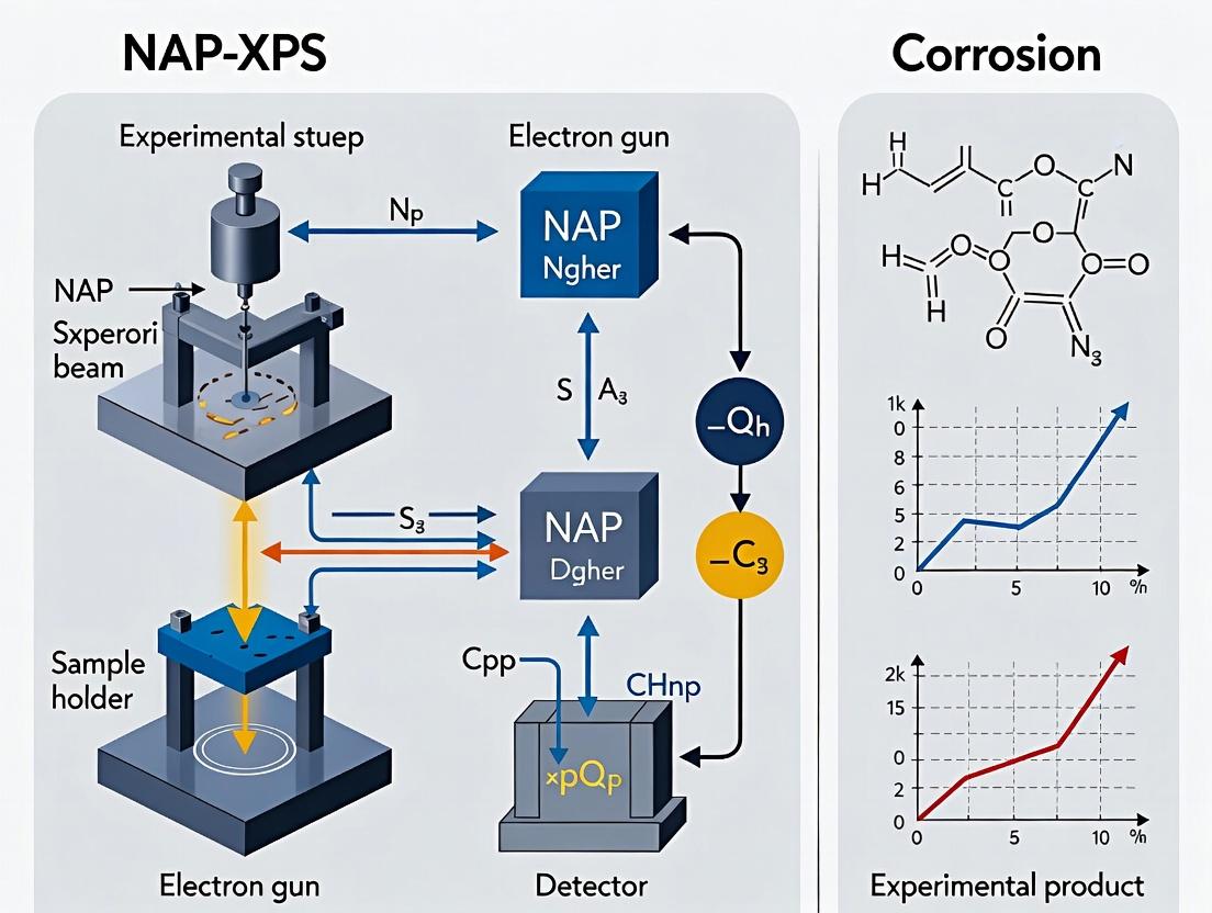
Unveiling Corrosion in Real Time: The Power of NAP-XPS for Biomaterial and Pharmaceutical Research
Near-Ambient Pressure X-ray Photoelectron Spectroscopy (NAP-XPS) has revolutionized corrosion science by enabling the direct, in-situ analysis of surfaces and interfaces under realistic gas or liquid environments.
Unveiling Corrosion in Real Time: The Power of NAP-XPS for Biomaterial and Pharmaceutical Research
Abstract
Near-Ambient Pressure X-ray Photoelectron Spectroscopy (NAP-XPS) has revolutionized corrosion science by enabling the direct, in-situ analysis of surfaces and interfaces under realistic gas or liquid environments. This article provides a comprehensive guide for researchers, scientists, and drug development professionals on applying NAP-XPS to corrosion studies. We explore its fundamental principles in probing oxide layer formation and chemical state changes, detail methodologies for monitoring dynamic processes like pitting and coating degradation, offer solutions for optimizing experiments and mitigating beam damage, and validate its efficacy by comparing it to traditional UHV-XPS, electrochemical techniques, and other in-situ methods. This synthesis highlights NAP-XPS as an indispensable tool for predicting material longevity, ensuring implant safety, and safeguarding pharmaceutical manufacturing equipment.
Beyond the Vacuum: How NAP-XPS Reveals the Fundamentals of Corrosion Chemistry
The study of corrosion mechanisms has long been hindered by the "pressure gap"—the disparity between the ultra-high vacuum (UHV) conditions of traditional surface science techniques and the realistic, often gas- or liquid-rich environments where corrosion occurs. Near-Ambient Pressure X-ray Photoelectron Spectroscopy (NAP-XPS) directly addresses this by enabling XPS analysis at pressures from 0.1 to 100+ mbar. Within the broader thesis on NAP-XPS for corrosion studies, this principle is foundational. It allows for the in situ and operando investigation of initial oxide formation, adsorbate layers, and inhibitor functionality on metal alloys under conditions mimicking real-world atmospheres, thereby bridging the gap between idealized models and practical corrosion science.
NAP-XPS bridges the pressure gap via a sophisticated differential pumping system that maintains the analyzer and detector at UHV while the sample region is at elevated pressure. Key performance metrics for a typical modern NAP-XPS system used in corrosion studies are summarized below.
Table 1: Comparative Performance Parameters of XPS Techniques
| Parameter | Traditional (UHV) XPS | NAP-XPS (Typical Range) | Relevance to Corrosion Studies |
|---|---|---|---|
| Operating Pressure | < 10⁻⁹ mbar | 0.1 – 25 mbar (up to 100+ mbar possible) | Enables studies in humid air, CO₂, O₂, or inhibitor vapor. |
| Probed Depth (IMFP) | ~1-3 nm (Al Kα) | Reduced to ~0.1-1 nm at 10 mbar due to scattering. | Surface-sensitive, ideal for thin oxide/hydroxide films & adsorbates. |
| Gas Interaction | None (static) | Dynamic flow, precise gas mixing. | Real-time monitoring of surface reactions (e.g., oxidation, passivation). |
| Sample Temperature | RT to ~700°C (limited) | RT to 600°C+ with gas presence. | Studies of thermal oxide growth or inhibitor decomposition. |
| Typical Energy Resolution | < 0.5 eV | < 0.5 – 1.0 eV (pressure-dependent broadening). | Maintains chemical state specificity (e.g., O²⁻ vs. OH⁻, metal vs. oxide). |
Detailed Application Notes & Protocols
Application Note 1:In SituOxidation of a Copper Alloy in Humid Air
Objective: To monitor the initial stages of patina formation on Cu-5Zn under realistic atmospheric conditions. Background: Corrosion in marine or urban atmospheres involves O₂ and H₂O. UHV studies cannot capture the role of adsorbed water layers.
Protocol:
- Sample Preparation: Polish Cu-5Zn coupon to mirror finish. Clean ultrasonically in ethanol and acetone. Introduce into NAP cell under inert gas (Ar) flow.
- Baseline Spectrum: Acquire survey and high-resolution spectra (Cu 2p, Zn 2p, O 1s, C 1s) at room temperature in 1 mbar of pure Ar.
- Gas Exposure Experiment: a. Switch gas supply to a pre-mixed humid synthetic air (80% N₂, 20% O₂, 95% relative humidity at 25°C). Stabilize pressure at 5 mbar. b. Heat sample to 50°C to accelerate kinetics. c. Acquire time-series high-resolution spectra (O 1s, Cu 2p, Cu LMM Auger) at 15-minute intervals for 6 hours.
- Data Analysis: Quantify the evolution of spectral components: metallic Cu/Zn, Cu₂O, CuO, ZnO, and the O 1s components for oxide (O²⁻) and hydroxide/water (OH⁻/H₂O).
Application Note 2: Evaluating a Volatile Corrosion Inhibitor (VCI)
Objective: To assess the adsorption mechanism and protective layer formation of a model VCI (dicyclohexylamine nitrite) on mild steel. Background: VCIs function by saturating enclosed atmospheres. NAP-XPS can directly probe the inhibitor/surface interface under relevant vapor pressures.
Protocol:
- VCI Chamber Setup: Place solid VCI powder in a temperature-controlled reservoir connected upstream of the NAP cell.
- Sample Preparation: Reduce native oxide on Fe sample by cycles of Ar⁺ sputtering and annealing (300°C) in the NAP cell preparation chamber. Transfer to analysis position.
- Dosing Experiment: a. Establish a flow of inert carrier gas (N₂) at 2 mbar. b. Heat VCI reservoir to 40°C to generate sufficient vapor pressure. c. Introduce VCI vapor into the carrier gas flow for 30 minutes. d. Acquire spectra before, during, and after dosing (Fe 2p, O 1s, N 1s, C 1s).
- Stability Test: After dosing, flush cell with pure, humid N₂ (5 mbar, 80% RH) for 1 hour to test inhibitor layer resilience.
- Data Analysis: Monitor N 1s signal for amine/nitrite species. Track Fe 2p line shape for suppression of oxide growth compared to a control experiment without VCI.
Visualization of Workflow & Principles
Diagram 1: NAP-XPS Principle for Corrosion Studies (75 chars)
Diagram 2: Protocol for In Situ Oxidation Study (90 chars)
The Scientist's Toolkit: Research Reagent Solutions
Table 2: Essential Materials for NAP-XPS Corrosion Experiments
| Item | Function & Specification | Relevance to Protocol |
|---|---|---|
| NAP-XPS System | Spectrometer with differential pumping, high-transmission analyzer, and a heated, gas-tight cell. | Core hardware enabling high-pressure analysis. |
| Precision Gas Mixing System | Mass flow controllers for up to 4 gases plus a temperature-controlled bubbler for humidity generation. | Essential for creating realistic gas mixtures (e.g., synthetic air with controlled RH). |
| Single Crystal or Polycrystalline Alloy Samples | Well-defined surfaces (e.g., Cu(111), Fe foil, AA2024 alloy). | Model systems for fundamental corrosion studies. |
| Volatile Corrosion Inhibitor (VCI) | High-purity compound (e.g., dicyclohexylamine nitrite, benzotriazole). | Probe molecule for studying protective adsorption layers in situ. |
| Calibration Reference | Sputtered gold foil or clean copper for energy scale calibration at pressure. | Accounts for work function changes under gas pressure. |
| Inert Carrier Gases | High-purity Ar, N₂ (99.999%+) for cleaning, baseline, and carrier streams. | Maintains sample cleanliness during transfers and controls vapor delivery. |
| Temperature-Controlled Vapor Doser | Heated reservoir with leak valve for controlled introduction of volatile compounds. | Critical for Application Note 2 (VCI studies). |
Application Notes: NAP-XPS for Corrosion Studies
Near-Ambient Pressure X-ray Photoelectron Spectroscopy (NAP-XPS) is a transformative analytical technique enabling the in-situ investigation of solid-gas and solid-liquid interfaces under realistic conditions. Within the broader thesis on advanced materials characterization for corrosion science, this technique is pivotal for retrieving three fundamental parameters: chemical states, layer thickness, and in-situ composition. This data is critical for constructing accurate models of initial corrosion mechanisms, passive film stability, and inhibitor functionality.
Core Data Retrieved via NAP-XPS
Table 1: Key Information Retrieved from NAP-XPS in Corrosion Studies
| Information Type | Typical NAP-XPS Method | Quantitative Output | Relevance to Corrosion Studies |
|---|---|---|---|
| Chemical States | High-resolution core-level spectra (e.g., Fe 2p, O 1s, Cr 2p) deconvolution. | Oxidation state percentages (e.g., % Fe⁰, Fe²⁺, Fe³⁺), compound identification (oxide, hydroxide, sulfate). | Identifies protective vs. non-protective oxides; monitors redox reactions in real time. |
| Layer Thickness | Angle-resolved NAP-XPS (AR-XPS) or modeling of photoelectron attenuation. | Thickness of surface oxide/hydroxide layers in Ångströms (Å). | Quantifies passive film growth; measures adsorbate or inhibitor layer thickness. |
| In-Situ Composition | Time-dependent, pressure-dependent spectral acquisition. | Atomic concentration (%) of elements (O, C, N, S, metal ions) as a function of time/pressure. | Tracks interfacial chemistry changes during exposure to corrosive gases (O₂, H₂S, H₂O) or inhibitor solutions. |
Detailed Experimental Protocols
Protocol 1:In-SituMonitoring of Passive Film Formation on a Metal Alloy
Objective: To determine the chemical state evolution and thickness of the oxide layer on a stainless-steel (SS) sample upon exposure to water vapor.
Materials & Reagents:
- Sample: Polished 316L SS coupon.
- Gases: High-purity O₂, H₂O (via temperature-controlled bubbler), Ar.
- NAP-XPS System equipped with a differentially pumped hemispherical analyzer and Al Kα source.
Procedure:
- Initial Preparation: Insert SS coupon into NAP cell. Evacuate to UHV (<1×10⁻⁷ mbar). Acquire survey and high-resolution spectra (Fe 2p, Cr 2p, O 1s, C 1s) of the clean, Ar⁺-sputtered surface.
- Oxide Growth: Introduce 1.0 mbar of high-purity O₂ for 30 minutes at room temperature. Acquire spectra.
- Water Vapor Exposure: Isolate O₂. Introduce H₂O vapor to a total pressure of 2.5 mbar. Maintain for 60 minutes.
- Data Acquisition: Collect high-resolution spectra every 10 minutes during steps 2 & 3.
- Post-Experiment: Pump down to UHV. Acquire final set of spectra.
Data Analysis:
- Chemical States: Deconvolute Fe 2p spectra using reference binding energies for metallic Fe (706.7 eV), FeO (~709.5 eV), Fe₂O₃ (~710.9 eV), and FeOOH (~711.8 eV).
- Layer Thickness: Calculate oxide thickness (d) using a bilayer model and the relative intensity ratio of oxide-to-metal peaks:
d = λ_oxide * sin(θ) * ln(1 + (I_oxide/I_metal)*(λ_metal/λ_oxide)), where λ is the inelastic mean free path and θ is the take-off angle (90° for standard NAP-XPS).
Protocol 2: Evaluation of a Corrosion Inhibitor Adsorption Layer
Objective: To measure the thickness and composition of an organic inhibitor film (e.g., benzotriazole, BTAH) on copper in a humid environment.
Materials & Reagents:
- Sample: Electropolished Cu coupon.
- Inhibitor: 10 mM Benzotriazole (BTAH) solution in ethanol.
- NAP-XPS System with a liquid/gas dosing manifold.
Procedure:
- Baseline: Clean Cu sample in UHV. Acquire Cu 2p, N 1s, C 1s, O 1s spectra.
- Inhibitor Application: Under Ar atmosphere (5 mbar), introduce BTAH-saturated vapor via a heated doser for 15 minutes. Alternatively, apply a droplet of inhibitor solution and allow to dry in the ante-chamber.
- Humidity Exposure: Introduce H₂O vapor to achieve 80% relative humidity (∼2.3 mbar at 25°C) in the analysis chamber.
- In-Situ Monitoring: Acquire N 1s and C 1s spectra every 5 minutes for 30 minutes to monitor film stability.
- Post-Analysis: Return to UHV for final high-resolution spectra.
Data Analysis:
- Composition: Use N 1s peak (∼399.5 eV for BTAH) to confirm inhibitor presence. Track C 1s and O 1s for potential contamination or hydrolysis.
- Thickness: Model inhibitor layer thickness using the attenuation of the underlying Cu 2p metal signal, assuming a homogeneous organic overlayer.
Visualization: NAP-XPS Corrosion Study Workflow
Diagram 1: NAP-XPS workflow for corrosion studies (100 chars)
The Scientist's Toolkit
Table 2: Essential Research Reagent Solutions & Materials for NAP-XPS Corrosion Experiments
| Item | Function in NAP-XPS Corrosion Studies |
|---|---|
| High-Purity Metal/Alloy Foils (≥99.99%) | Provides a well-defined, reproducible substrate for fundamental studies of oxidation and corrosion mechanisms. |
| Certified Corrosive Gases (O₂, H₂S, CO₂, SO₂) | Creates realistic atmospheric corrosion environments inside the NAP cell for in-situ exposure. |
| Temperature-Controlled Water Vapor Doser | Precisely controls relative humidity (RH) in the chamber, critical for studying aqueous corrosion and hydrolysis. |
| Electrochemical Cell for Operando NAP-XPS | Enables simultaneous electrochemical polarization and XPS analysis for studying active corrosion processes. |
| Organic Corrosion Inhibitors (e.g., BTAH, 8-HQ) | Used to form protective adsorbed layers on metals; their persistence and chemistry under humid conditions can be studied. |
| Inert Calibration Gas (e.g., Ar, Ne) | Used for charge referencing (e.g., Adventitious C 1s correction) and as a diluent or carrier gas. |
| Sputter Ion Gun (Ar⁺, Kr⁺) | Cleans sample surfaces prior to experiments and creates depth profiles by sequential sputtering and analysis. |
| Standard Reference Materials (e.g., Au, Cu, Ag foils) | Essential for binding energy scale calibration and verifying spectrometer performance. |
This Application Note details the protocols for studying the earliest stages of metal oxidation and passivation, a central pillar of our broader thesis on Operando NAP-XPS for Dynamic Corrosion Studies. Understanding the formation of the initial oxide layer (1-5 nm) is critical for predicting material stability. Near-Ambient Pressure X-ray Photoelectron Spectroscopy (NAP-XPS) is uniquely positioned to probe these critical interfaces in situ under controlled gas and humidity environments, bridging the "pressure gap" between traditional UHV studies and real-world conditions.
Key Experimental Protocols
Protocol A: In Situ Oxidation Kinetics of Pure Polycrystalline Chromium
Objective: To quantify the initial oxide growth law on a model metal (Cr) under controlled O₂ partial pressure at room temperature.
Methodology:
- Sample Preparation: A high-purity (99.99%) polycrystalline Cr coupon is electropolished in a perchloric acid-acetic acid solution (8:92 vol%), rinsed with ethanol, and dried under argon.
- Initial Characterization: Introduce the sample into the NAP-XPS chamber. Under UHV (1×10⁻⁸ mbar), acquire survey and high-resolution spectra (Cr 2p, O 1s, C 1s) to establish the clean surface state.
- Oxidation Experiment:
- Set the sample temperature to 25°C.
- Introduce research-grade O₂ gas to the analysis chamber to a target pressure of 1.0 mbar.
- Initiate a time-series experiment. Acquire high-resolution Cr 2p spectra at fixed intervals (e.g., 0, 30, 60, 120, 300, 600 seconds).
- Maintain constant photon energy and pass energy.
- Data Analysis:
- Fit Cr 2p spectra with components for metallic Cr(0) and oxide/hydroxide species (Cr³⁺).
- Calculate oxide thickness (d) using a modified Beer-Lambert relationship:
d = λ_oxide * sin(θ) * ln(1 + (I_oxide/I_metal * K)), where λ_oxide is the attenuation length, θ is the take-off angle, I is intensity, and K is a sensitivity factor ratio. - Plot oxide thickness vs. time to determine the growth law (logarithmic, parabolic, etc.).
Protocol B: Passivation Initiation on Fe-Cr Alloy in Humid Atmosphere
Objective: To deconvolute the roles of O₂ and H₂O in the formation of the initial passive film on a model stainless steel (Fe-20Cr).
Methodology:
- Sample Preparation: Fe-20Cr alloy sample is prepared via magnetron sputtering on a conductive substrate to ensure uniformity, followed by Ar⁺ sputter cleaning in the load-lock chamber.
- Sequential Exposure Workflow:
- Step 1 (Dry O₂): Acquire reference spectra. Expose the clean surface to 0.5 mbar pure O₂ for 10 mins. Acquire Fe 2p, Cr 2p, O 1s spectra.
- Step 2 (Humid Introduction): While maintaining total pressure, introduce H₂O vapor via a leak valve to achieve a relative humidity (RH) of 5% (P_H₂O ≈ 0.016 mbar at 25°C). Monitor spectral evolution for 20 mins.
- Step 3 (Increased Humidity): Increase PH₂O to achieve 50% RH (PH₂O ≈ 0.16 mbar). Continue acquisition for 30 mins.
- Spectra Deconvolution: Fit O 1s spectra with components for O²⁻ (oxide), OH⁻ (hydroxide), and H₂O (adsorbed water). Correlate the evolution of these components with changes in metal cation (Cr³⁺, Fe³⁺, Fe²⁺) ratios from the metal 2p spectra.
Data Presentation
Table 1: Quantified Oxide Growth on Polycrystalline Cr at 1.0 mbar O₂, 25°C
| Time (s) | Cr(0) 2p₃/₂ BE (eV) | Cr³⁺ 2p₃/₂ BE (eV) | Ioxide / Imetal | Calculated Thickness (Å) |
|---|---|---|---|---|
| 0 | 574.0 ± 0.1 | - | 0.00 | 0.0 |
| 30 | 574.0 ± 0.1 | 576.6 ± 0.2 | 0.15 ± 0.03 | 2.1 ± 0.4 |
| 60 | 574.1 ± 0.1 | 576.6 ± 0.2 | 0.24 ± 0.03 | 3.3 ± 0.4 |
| 120 | 574.1 ± 0.1 | 576.7 ± 0.2 | 0.38 ± 0.04 | 5.0 ± 0.5 |
| 300 | 574.1 ± 0.1 | 576.7 ± 0.2 | 0.55 ± 0.05 | 7.1 ± 0.6 |
| 600 | 574.1 ± 0.1 | 576.7 ± 0.2 | 0.67 ± 0.05 | 8.5 ± 0.6 |
BE = Binding Energy. Growth follows a logarithmic rate law: d = A * ln(t) + B.
Table 2: O 1s Species Evolution on Fe-20Cr Alloy During Humid Exposure
| Exposure Condition | O²⁻ (Oxide) (%) | OH⁻ (Hydroxide) (%) | H₂O (ads/physisorbed) (%) | Cr³⁺/Fe³⁺ Ratio* |
|---|---|---|---|---|
| Clean Surface (UHV) | - | - | - | - |
| 0.5 mbar Dry O₂ (10 min) | 78 ± 3 | 22 ± 3 | 0 | 2.5 ± 0.3 |
| + 5% RH (20 min) | 65 ± 4 | 32 ± 3 | 3 ± 1 | 3.1 ± 0.4 |
| + 50% RH (30 min) | 52 ± 5 | 41 ± 4 | 7 ± 2 | 4.0 ± 0.5 |
*Calculated from fitted metal 2p spectral intensities.*
Visualizations
In Situ Oxidation Kinetics Experimental Workflow
Passivation Pathways: Dry Oxidation to Hydrated Film Growth
The Scientist's Toolkit
Table 3: Essential Research Reagent Solutions & Materials
| Item | Function in NAP-XPS Corrosion Studies |
|---|---|
| High-Purity Metal Foils (Cr, Fe, Ni, Al) | Model systems for fundamental oxidation kinetics studies without complicating alloying effects. |
| Well-Defined Binary/ Ternary Alloys (e.g., Fe-Cr, Ni-Cr) | Model systems for studying synergistic passivation effects and elemental segregation. |
| Research-Grade Gases (O₂, N₂, CO₂, H₂S) | Ultrapure gases for creating controlled, contaminant-free reaction atmospheres. |
| Humidity Generation System | Precise leak valve or bubbler system for introducing known partial pressures of H₂O vapor. |
| Electropolishing Electrolytes | For producing smooth, reproducible, and native-oxide-free initial metal surfaces. |
| Sputter Gas (Ar⁺, 99.9999%) | For in situ surface cleaning in the UHV preparation chamber prior to NAP-XPS experiments. |
| Certified XPS Reference Samples (Au, Cu, Ag) | For precise binding energy scale calibration and instrument function verification. |
This application note is framed within a broader thesis investigating the application of Near-Ambient Pressure X-ray Photoelectron Spectroscopy (NAP-XPS) for studying initial corrosion and passivation mechanisms. Titanium alloys, particularly Ti-6Al-4V, are predominant in orthopedic and dental implants due to their excellent biocompatibility and corrosion resistance, which stems from a stable, self-limiting oxide layer (TiO₂). However, the precise mechanisms and kinetics of early-stage oxide formation in physiologically relevant environments remain critical for improving long-term implant performance. NAP-XPS uniquely allows for the monitoring of these surface chemical states in the presence of trace gases and water vapor, simulating real-world conditions impossible with conventional ultra-high vacuum XPS.
Application Notes: Key Insights on Early-Stage Oxidation
Recent studies utilizing NAP-XPS have elucidated the dynamic evolution of the titanium alloy surface under controlled environments. The process is not merely the growth of stoichiometric TiO₂ but involves a complex interplay of suboxide formation, hydroxylation, and competitive adsorption.
Table 1: Quantitative Evolution of Surface Species on Ti-6Al-4V During Early Oxidation (at 300K, 1 mbar O₂)
| Time (Minutes) | Ti⁰ (Metallic) Atomic % | Ti²⁺ (TiO) Atomic % | Ti³⁺ (Ti₂O₃) Atomic % | Ti⁴⁺ (TiO₂) Atomic % | O / Ti Ratio | OH⁻ / O²⁻ Ratio |
|---|---|---|---|---|---|---|
| 0 (Sputtered) | 65.2 | 12.5 | 8.1 | 14.2 | 0.8 | 0.05 |
| 5 | 38.7 | 18.9 | 22.3 | 20.1 | 1.4 | 0.15 |
| 15 | 15.4 | 15.6 | 25.8 | 43.2 | 2.1 | 0.22 |
| 30 | 5.1 | 8.3 | 18.4 | 68.2 | 2.6 | 0.30 |
| 60 | <2.0 | 4.5 | 12.1 | 81.4 | 2.8 | 0.35 |
Key Findings:
- Sequential Oxidation: Oxidation proceeds via sequential electron transfer: Ti⁰ → Ti²⁺ → Ti³⁺ → Ti⁴⁺. The Ti³⁺ (Ti₂O₃) state acts as a metastable intermediate, persisting even after 60 minutes.
- Hydroxylation: The presence of trace water vapor (simulating physiological humidity) leads to significant surface hydroxylation (OH⁻ groups), as indicated by the increasing OH⁻/O²⁻ ratio. This hydroxylated layer is crucial for biomolecule adhesion in vivo.
- Al and V Oxidation: Concurrently, Al oxidizes rapidly to Al₂O₃, and V forms mixed V⁴⁺/V⁵⁺ oxides. NAP-XPS tracks these alloying elements, showing their segregation or encapsulation within the growing TiO₂ matrix, which influences local electrochemical behavior.
Experimental Protocols
Protocol: NAP-XPS Monitoring of Oxide Growth on Ti-6Al-4V
Objective: To characterize the chemical state evolution of a Ti-6Al-4V surface during initial oxidation under near-ambient conditions of oxygen and water vapor.
I. Sample Preparation:
- Material: Ti-6Al-4V ELI (Grade 23) disc, 10mm diameter x 2mm thickness.
- Polishing: Sequentially wet-polish with SiC paper from P400 to P4000 grit, followed by colloidal silica suspension (0.04 µm) to a mirror finish.
- Cleaning: Ultrasonicate in acetone, ethanol, and ultrapure water (18.2 MΩ·cm) for 10 minutes each. Dry under a stream of Argon.
- In-situ Cleaning: Introduce the sample into the NAP-XPS analysis chamber. Perform cycles of Ar⁺ sputtering (1 keV, 5 µA, 10 minutes) until the survey spectrum shows minimal oxygen and carbon contamination (<5 at.% combined).
II. NAP-XPS Experiment Setup:
- Instrument: Use a NAP-XPS system equipped with a Al Kα monochromatic X-ray source (1486.7 eV) and a high-transmission electron energy analyzer.
- Baseline Spectrum: Acquire high-resolution spectra of Ti 2p, O 1s, Al 2p, V 2p, and C 1s under UHV conditions (<1×10⁻⁷ mbar) as a reference.
- Gas Introduction: Introduce a 9:1 mixture of research-grade O₂ and H₂O vapor into the analysis chamber. Pre-mix gases using calibrated mass flow controllers. Stabilize pressure at 1.0 mbar.
- Time-series Acquisition: Start data acquisition immediately upon pressure stabilization. Collect high-resolution spectra of the core levels (Ti 2p, O 1s) every 5 minutes for the first 30 minutes, then every 10 minutes for the next 90 minutes. Use a pass energy of 20 eV and step size of 0.05 eV. Maintain sample temperature at 25°C ± 1°C.
III. Data Processing & Analysis:
- Calibration: Shift all spectra by aligning the adventitious C 1s peak to 284.8 eV.
- Peak Fitting: Deconvolute the Ti 2p₃/₂ spectrum using symmetrical Voigt functions with fixed spin-orbit splitting (5.7 eV) and area ratio (2:1).
- Component Binding Energies: Ti⁰ (453.9 eV), Ti²⁺ (455.0 eV), Ti³⁺ (456.7 eV), Ti⁴⁺ (458.8 eV).
- Quantification: Calculate atomic concentrations using instrument-specific sensitivity factors. Track the O/Ti ratio and the OH⁻ component (O 1s ~531.5 eV) relative to the lattice O²⁻ component (O 1s ~530.1 eV).
Protocol:In-SituElectrochemical Polarization Coupled with NAP-XPS
Objective: To correlate electrochemical potential with surface chemical changes during anodic polarization in a thin electrolyte film.
- Cell Setup: Integrate a miniaturized three-electrode electrochemical cell into the NAP-XPS sample stage (working electrode: Ti-6Al-4V, counter: Pt wire, pseudo-reference: Ag/AgCl wire).
- Electrolyte Introduction: Introduce a micro-droplet of simulated body fluid (SBF, pH 7.4) onto the sample surface, forming a thin film (~µm).
- Environment: Maintain chamber pressure at ~15 mbar to stabilize the liquid film.
- Experiment: Perform linear sweep voltammetry (scan rate: 0.5 mV/s from open circuit potential to +1.0 V). Simultaneously, trigger NAP-XPS snapshot spectra at key potentials (OCP, passivation onset, +0.5V, +1.0V).
- Analysis: Correlate the current density with the Ti⁴⁺/Ti⁰ ratio and the emergence of Ca/P species from the SBF to understand phosphate integration into the passive layer.
Visualizations: Pathways and Workflows
Title: Sequential Oxidation Pathway of Titanium Surface
Title: NAP-XPS Experimental Workflow for Corrosion Tracking
The Scientist's Toolkit: Research Reagent Solutions
Table 2: Essential Materials & Reagents for NAP-XPS Corrosion Studies of Implants
| Item Name | Function / Relevance | Specification / Notes |
|---|---|---|
| Ti-6Al-4V ELI (Grade 23) | Primary substrate. ELI (Extra Low Interstitial) grade minimizes inclusions, providing a more consistent surface for fundamental studies. | Disc format, 10-15mm diameter. Surface finish: mirror polished. |
| Research-Grade Oxygen (O₂) | Primary oxidant gas for simulating early-stage passivation. High purity is critical to avoid introducing confounding surface contaminants. | 99.999% purity, with certified hydrocarbon <0.5 ppm. |
| Deuterated Water (D₂O) Vapor | Used instead of H₂O in studies utilizing mass spectrometry detection to avoid background interference. Provides insights into hydroxylation kinetics. | 99.9% D atom % purity. Introduced via a calibrated, heated vapor source. |
| Simulated Body Fluid (SBF) | Electrolyte for in-situ electrochemistry experiments. Its ion concentration mirrors human blood plasma to ensure physiological relevance. | Prepared per Kokubo recipe, pH adjusted to 7.40 at 36.5°C, sterile filtered. |
| Colloidal Silica Polishing Suspension | Provides final, damage-free surface finish crucial for reproducible initial surface conditions before oxidation. | 0.04 µm (40 nm) particle size, high-purity. |
| Argon (Ar) Sputtering Gas | Used for in-situ sample surface cleaning within the analysis chamber to remove native oxide and contaminants prior to experiment. | 99.9999% purity. |
| XPS Sensitivity Factor Database | Enables accurate quantification of atomic percentages from photoelectron peak areas. Specific to instrument and source. | Provided by spectrometer manufacturer, regularly updated. |
In-Situ and Operando Protocols: Applying NAP-XPS to Dynamic Corrosion Scenarios
Near-ambient pressure X-ray photoelectron spectroscopy (NAP-XPS) is a transformative technique for studying corrosion processes under realistic environmental conditions, bridging the "pressure gap" between traditional ultra-high vacuum (UHV) XPS and practical applications. Within this broader thesis, the choice between gas-phase and thin liquid electrolyte layer experimental setups is critical. Gas-phase studies probe the initial interactions of corrosive gases (e.g., O₂, CO₂, H₂S) with metal/alloy surfaces, modeling atmospheric corrosion. In contrast, thin liquid electrolyte layer studies investigate interfacial electrochemistry and ion-specific effects under controlled aqueous environments, modeling immersion or condensed layer corrosion. This application note details protocols and considerations for both approaches.
Core Comparative Analysis
Quantitative Comparison of Setup Parameters
Table 1: Key Operational Parameters for Gas Phase vs. Thin Liquid Layer NAP-XPS
| Parameter | Gas Phase Studies | Thin Liquid Electrolyte Layer Studies |
|---|---|---|
| Typical Pressure Range | 0.1 - 20 mbar | 10 - 25 mbar (for water stability) |
| Sample Temperature Control | -20°C to 600°C (for simulating thermal conditions) | 0°C to 80°C (often near room temperature) |
| Probed Depth | 1-10 nm (surface and near-surface) | 1-5 nm (liquid/vapor interface & buried solid/liquid interface) |
| Liquid Thickness (if applicable) | Not applicable | 10 nm to 1 µm (requires precise control) |
| Key Detectable Species | Metal, oxides, hydroxides, adsorbed gas molecules (O, OH, CO₃) | Solvated ions, electric double layer (EDL) components, hydrated oxides, precipitates |
| Electrochemical Control | Not typically available | Possible with micro-reactor cells (applied potential) |
| Main Challenge | Maintaining homogeneous gas composition; beam damage to adsorbates. | Achieving and verifying uniform, stable thin layer; minimizing X-ray-induced water radiolysis. |
| Primary Corrosion Insights | Oxide growth kinetics, initial adsorbate reactions, gas reduction mechanisms. | Ion adsorption, passivation/depassivation, pH effects, electrochemical potentials. |
Table 2: Common Experimental Conditions from Recent Literature (2023-2024)
| Study Focus | Setup Type | Gas Composition | Pressure (mbar) | Electrolyte | Key Finding (Quantitative) |
|---|---|---|---|---|---|
| Cu oxidation | Gas Phase | 1% O₂ in N₂ | 1.0 | N/A | Oxide thickness saturated at ~2.5 nm after 180 min exposure. |
| Stainless steel passivation | Thin Layer | Water vapor (saturated) | 15 | 0.1M NaCl (pH 6) | Cr₂O₃/Cr(OH)₃ ratio in passive film increased from 1:2 to 3:1 over 1 hour. |
| CO₂ corrosion of Fe | Gas Phase | 5% CO₂, 95% H₂O (g) | 3.0 | N/A | FeCO₃ formation rate constant: ~0.03 nm/min at 25°C. |
| Mg alloy degradation | Thin Layer | Ar (carrier) | 12 | 0.01M Na₂SO₄ | Mg(OH)₂ layer growth ~5 nm/hour; Cl⁻ ingress detected after 30 min. |
Detailed Experimental Protocols
Protocol A: Gas Phase Corrosion Studies (e.g., O₂ on Copper)
Objective: To study the initial kinetics of copper oxide formation under low-pressure oxygen.
Materials & Pre-Treatment:
- Sample: Polycrystalline Cu foil (99.99%).
- Pre-cleaning: Sputter with Ar⁺ ions (2 keV, 5 µA) for 15 minutes in UHV preparation chamber to remove native oxide and contaminants.
- Transfer: Transfer sample under UHV to the NAP-XPS analysis chamber.
Procedure:
- Baseline Measurement:
- Isolate analysis chamber, ensure initial pressure <1x10⁻⁷ mbar.
- Acquire high-resolution spectra for Cu 2p, O 1s, C 1s, and valence band regions using Al Kα source (1486.6 eV) and pass energy of 20 eV.
- Gas Introduction:
- Backfill the analysis chamber with research-grade O₂ (99.999%) to a target pressure of 1.0 mbar using a precision leak valve.
- Monitor pressure with a capacitive manometer.
- In-Situ Exposure & Data Acquisition:
- Start time-resolved measurements. Program the spectrometer to cycle through key spectral regions (e.g., Cu 2p₃/₂, O 1s) every 5 minutes for 3 hours.
- Maintain constant sample temperature at 25°C using a sample cooling/heating stage.
- Post-Exposure Analysis:
- Pump down the chamber to UHV.
- Acquire a final, detailed full spectral scan.
- Data Analysis:
- Fit Cu 2p spectra to quantify metallic Cu⁰, Cu⁺ (Cu₂O), and Cu²⁺ (CuO) components using known binding energy references and satellite structures.
- Calculate oxide thickness using a layer model and the relative attenuation of the metallic Cu substrate signal.
Protocol B: Thin Liquid Electrolyte Layer Studies (e.g., NaCl on Iron)
Objective: To investigate the formation and composition of the passive film on iron under a nanoscale aqueous electrolyte layer.
Materials & Pre-Treatment:
- Sample: High-purity Fe (110) single crystal.
- Electrolyte: 0.1M NaCl solution, prepared with Millipore water (18.2 MΩ·cm) and degassed with Ar for 30 minutes.
- Cell: Specially designed micro-fluidic NAP cell with Si₃N₄ or graphene membrane window for X-ray transparency.
Procedure:
- Sample Preparation & Transfer:
- Sputter-clean Fe sample in UHV, then transfer to the NAP cell within the analysis chamber under inert atmosphere.
- Electrolyte Layer Formation:
- Isolate the cell volume. Introduce water vapor to saturation pressure (~23 mbar at 25°C).
- Introduce the degassed 0.1M NaCl electrolyte via a micro-capillary inlet, forming a thin layer via condensation/capillary forces. Layer thickness is controlled by the vapor pressure and monitored via the O 1s signal ratio between liquid water and gas-phase water.
- In-Situ Measurement:
- Acquire spectra for Fe 2p, O 1s, Cl 2p, Na 1s, and valence band.
- Focus on the O 1s region to distinguish between liquid H₂O (∼536.0 eV), hydroxide in film (∼531.5 eV), and oxide (∼530.0 eV).
- Potential Control (if equipped):
- Apply a controlled potential (e.g., +0.2 V vs. pseudo-reference) using a micro-potentiostat connected to the sample (working electrode) and a Pt wire (counter electrode).
- Monitor spectral changes as a function of applied potential to simulate anodic passivation.
- Post-Experiment:
- Carefully drain and pump away the electrolyte.
- Acquire spectra of the post-corrosion surface under "dry" conditions (low water vapor pressure).
- Data Analysis:
- Deconvolute Fe 2p spectra to quantify Fe⁰, Fe²⁺, Fe³⁺ states.
- Analyze the OH⁻/O²⁻ ratio from O 1s to determine film hydration.
- Track Cl 2p signal intensity as a function of time to monitor chloride adsorption/ingress.
Visualizing the Experimental Decision Pathway
Diagram Title: NAP-XPS Corrosion Setup Selection Pathway
The Scientist's Toolkit: Essential Research Reagents & Materials
Table 3: Key Reagents and Materials for NAP-XPS Corrosion Studies
| Item | Function in Experiment | Critical Specification/Note |
|---|---|---|
| High-Purity Metal Samples (Foils, Single Crystals) | The substrate for corrosion studies. Reproducible surface structure and composition are vital. | 99.99% purity or higher. Well-defined crystallographic orientation for single crystals. |
| Research Grade Gases (O₂, CO₂, H₂S, N₂, Ar) | Create the corrosive or inert gas-phase environment in the NAP cell. | 99.999% purity or better, with dedicated, clean gas lines to avoid contamination. |
| Ultra-Pure Water (Milli-Q or equivalent) | Base for all electrolyte solutions. Minimizes contaminant interference. | Resistivity 18.2 MΩ·cm at 25°C, Total Organic Carbon (TOC) < 5 ppb. |
| High-Purity Salts (NaCl, Na₂SO₄, etc.) | Provide ionic species (e.g., Cl⁻, SO₄²⁻) to study their role in corrosion. | 99.99% trace metals basis. Bake before use if necessary to remove moisture. |
| Micro-Fluidic Electrochemical Cell | Enables formation of thin liquid layers and application of potential in situ. | Must have an X-ray transparent window (e.g., Si₃N₄, graphene). Compatible with spectrometer. |
| Reference Electrodes (Micro) | Provide stable potential reference in thin-layer electrochemistry. | Ag/AgCl or reversible hydrogen electrode (RHE) miniaturized for cell integration. |
| Ion Sputter Gun (Ar⁺) | For in-situ sample surface cleaning prior to experiment. | Differential pumping required for operation in or near preparation chamber. |
| Temperature-Controlled Sample Stage | Regulates sample temperature to simulate real-world conditions or control reaction rates. | Range from cryogenic (-150°C) to high temperature (600°C) with stability of ±0.5°C. |
| Graphene or Si₃N₄ Membranes | Used as protective covers or cell windows to separate environments while allowing X-ray penetration. | Graphene offers superior conductivity and thinness; Si₃N₄ offers mechanical robustness. |
Application Notes
The application of Near-Ambient Pressure X-ray Photoelectron Spectroscopy (NAP-XPS) within corrosion science research provides an unprecedented capability to monitor active, dynamic interfacial electrochemical processes under conditions that closely mimic operational environments. This directly addresses the thesis core that traditional ultra-high vacuum (UHV) XPS fails to capture the critical role of adsorbed water layers, solution chemistry, and transient species in corrosion initiation and propagation. By allowing analysis at pressures of several tens of mbar, NAP-XPS bridges the "pressure gap," enabling real-time chemical state analysis during pitting, galvanic coupling, and coating degradation.
For Pitting Corrosion: NAP-XPS enables the tracking of chloride ion adsorption, the breakdown of passive oxide films (e.g., on stainless steels or Al alloys), and the subsequent formation of metastable and stable pits. The technique can identify the chemical states of cations (e.g., Fe²⁺, Cr³⁺, Ni²⁺) within the pit environment and the evolution of hydroxide/oxyhydroxide species at the pit mouth, crucial for understanding repassivation kinetics.
For Galvanic Coupling: The thesis leverages NAP-XPS to study charge transfer processes at the junction of dissimilar metals (e.g., Al coupled to Cu or steel coupled to Zn) in humid atmospheres. It can spatially and chemically resolve the anodic dissolution site (e.g., Zn or Al oxidation) and the cathodic site (e.g., oxygen reduction on Cu or steel), mapping potential gradients and interfacial pH changes through shifts in O 1s and metal core-level spectra.
For Coating Breakdown: NAP-XPS is ideal for probing the ingress of water and electrolytes through polymer coatings and the subsequent delamination or underfilm corrosion at the coating/metal interface. It can monitor the formation of corrosion products (e.g., iron oxides, zinc salts) beneath intact coatings, providing early failure indicators long before macroscopic blistering occurs.
Table 1: Characteristic NAP-XPS Binding Energy Shifts in Corrosion Studies
| Element & State | Typical BE (eV) | Shift in Corroded State | Process Indicated |
|---|---|---|---|
| Fe (metallic) | 706.7 ± 0.1 | - | Uncorrupted substrate |
| Fe²⁺ (FeO) | 709.5 - 710.5 | +2.8 to +3.8 | Initial oxidation, underfilm corrosion |
| Fe³⁺ (Fe₂O₃/FeOOH) | 710.8 - 711.5 | +4.1 to +4.8 | Passive layer, stable rust |
| Cr (metallic) | 574.1 ± 0.1 | - | Alloy element |
| Cr³⁺ (Cr₂O₃) | 576.6 - 577.2 | +2.5 to +3.1 | Passivation layer |
| O 1s (Oxide) | 529.8 - 530.5 | - | Lattice oxygen |
| O 1s (OH/H₂O) | 531.2 - 533.5 | +1.4 to +3.7 | Hydroxyl, adsorbed water (key in NAP) |
| Cl 2p (adsorbed) | 198.5 - 199.5 | - | Chloride initiation of pitting |
| Zn²⁺ (ZnO) | 1021.8 ± 0.2 | - | Galvanic coating oxidation |
Table 2: NAP-XPS Operational Parameters for In Situ Corrosion Monitoring
| Parameter | Typical Setting for Corrosion Studies | Rationale |
|---|---|---|
| Pressure | 5 - 15 mbar H₂O or O₂/H₂O mix | Maintains several monolayers of water, mimics humid air. |
| Temperature | 25°C - 80°C | Accelerated testing, study temperature-dependent kinetics. |
| X-ray Source | Al Kα (1486.6 eV), Monochromated | High spectral resolution for fine chemical shifts. |
| Spot Size | 50 - 400 µm | Balance between spatial resolution and signal intensity for mapping. |
| In Situ Stimuli | Potentiostatic control, droplet deposition | Actively drive corrosion while analyzing. |
Experimental Protocols
Protocol 1:In SituPitting Corrosion Initiation on Stainless Steel
Objective: To monitor the chemical evolution of the passive film on AISI 316L stainless steel during chloride-induced breakdown.
Materials: See "Research Reagent Solutions" table.
Procedure:
- Sample Preparation: Cut 316L coupon to 10x10x2 mm. Sequentially polish to 1 µm diamond finish. Clean ultrasonically in acetone and ethanol for 10 min each. Dry under Ar stream.
- NAP-XPS Pre-exposure Baseline: Introduce sample into NAP-XPS chamber. Evacuate to <1x10⁻⁶ mbar. Acquire high-resolution spectra of Fe 2p, Cr 2p, Ni 2p, O 1s, and C 1s under UHV to characterize the air-formed passive layer.
- Humid Environment Establishment: Introduce high-purity water vapor into the analysis chamber to a pressure of 8 mbar (≈95% RH at 25°C). Stabilize for 15 min. Acquire O 1s spectrum to confirm presence of adsorbed H₂O (BE ~533 eV).
- Chloride Introduction & In Situ Pitting: Using the micro-doser, deposit a 100 nL droplet of 1.0 M NaCl solution onto the sample surface in situ. Immediately begin a time-resolved sequence of XPS scans over the droplet area.
- Data Acquisition: Perform rapid sequential scans over Fe 2p and Cr 2p regions every 5 minutes for 2 hours. Monitor the decrease in Cr³⁺/Cr⁰ ratio and the increase in Fe²⁺ and O 1s hydroxyl signal as the pit initiates and propagates.
- Post-Exposure Analysis: Pump out water vapor. Acquire final high-resolution spectra under UHV. Perform spatial mapping of Cl distribution.
Protocol 2: Galvanic Coupling Dynamics Between Zn and Fe
Objective: To spatially resolve anodic and cathodic processes on a Zn/Fe model couple in a humid atmosphere.
Procedure:
- Sample Fabrication: Create a model galvanic couple by depositing a 500 nm Zn film (masked) adjacent to a pure Fe foil, leaving a 100 µm gap. Ensure electrical contact at the back.
- Baseline Mapping: Under UHV, perform an XPS map (step size 50 µm) across the Zn/Fe junction for Zn 2p, Fe 2p, and O 1s.
- In Situ Coupling in Humid Air: Introduce a mixture of O₂ (2 mbar) and H₂O (8 mbar) for a total pressure of 10 mbar. Connect the sample to an external zero-resistance ammeter (ZRA) circuit in situ to measure galvanic current.
- Time-Lapsed Chemical Mapping: At 30-minute intervals, acquire chemical state maps over the junction. Key metrics: Zn²⁺/Zn⁰ ratio (anodic dissolution on Zn), Fe³⁺/Fe⁰ ratio, and O 1s component ratio of oxide vs. hydroxide (cathodic OH⁻ generation on Fe).
- Correlate Electrochemistry & Chemistry: Correlate spikes in galvanic current with the spatial expansion of the Zn oxidation front and the increasing hydroxide signal on the Fe cathode.
Protocol 3: Coating Breakdown and Underfilm Corrosion
Objective: To observe the ingress of water and ions through a polymer coating and the subsequent onset of underfilm corrosion on steel.
Procedure:
- Coated Sample Preparation: Apply a 5 µm thick epoxy coating (with 0.1 wt.% tracer like F for XPS identification) onto a polished low-carbon steel panel. Create a defined artificial defect (scratch to metal) using a calibrated tip.
- Initial Interface Characterization: Use angle-resolved NAP-XPS (at 5 mbar N₂) to non-destructively depth-profile the intact coating near the scratch, probing the C 1s, O 1s, and F 1s signals.
- In Situ Exposure: Introduce D₂O vapor (10 mbar). Use the mass difference to track water ingress specifically via the O 1s shift. Monitor the defect and adjacent intact coating area.
- Induction of Breakdown: After 1 hour, introduce 0.1 mbar of acetic acid (CH₃COOH) vapor to simulate an aggressive environment. Continue time-lapsed spectroscopy.
- Monitor Underfilm Corrosion: Focus on the intact coating adjacent to the scratch. Look for the appearance of Fe²⁺ signals through the coating, and a change in the C 1s spectrum (ester hydrolysis) of the epoxy, indicating coating degradation and underfilm corrosion initiation.
The Scientist's Toolkit: Research Reagent Solutions
Table 3: Essential Materials for NAP-XPS Corrosion Experiments
| Item | Function in Experiment |
|---|---|
| High-Purity Metal Alloys (e.g., 316L SS, AA2024) | Model substrates for pitting and coupling studies. Well-defined composition is critical. |
| Polymer-Coated Metal Panels (e.g., Epoxy on Steel) | Model systems for coating degradation studies. Coating thickness must be XPS-transparent (<10 µm). |
| Deionized Water & D₂O (99.9%) | Source of humid atmospheres. D₂O allows tracking of water-specific signals. |
| NaCl, Na₂SO₄, HCl (High Purity) | Electrolytes for droplet deposition or vapor-phase introduction to initiate corrosion. |
| Calibrated Micro-Doser/Syringe System | For precise in situ deposition of picoliter to nanoliter electrolyte droplets in the NAP cell. |
| In Situ Electrochemical Kit for NAP-XPS | Includes micro-positionable electrodes, potentiostat, and electrically biased sample holder for coupling studies. |
| Certified Gas Mixtures (O₂, CO₂, N₂ with ppm H₂S) | For creating complex atmospheric environments (marine, industrial). |
| Sputter Ion Source (Ar⁺, C₆₀⁺) | For gentle, in situ depth profiling of corrosion products or coating interfaces. |
Visualizations
Title: NAP-XPS Protocol for In Situ Pitting Corrosion
Title: Chemical & Spatial Resolution of Galvanic Processes
Title: NAP-XPS Tracking of Coating Breakdown Steps
1. Introduction & Thesis Context Within the broader thesis on Near-Ambient Pressure X-ray Photoelectron Spectroscopy (NAP-XPS) for corrosion research, this application note addresses a critical gap: the real-time, in situ investigation of organic corrosion inhibitor performance. Traditional ex situ methods fail to capture dynamic adsorption kinetics, competitive processes, and the evolution of protective layers under realistic environmental conditions (e.g., in the presence of water vapor). This protocol details how NAP-XPS bridges this gap, enabling direct quantification of inhibitor adsorption, displacement of corrosive species, and the chemical characterization of the forming protective film, all in real time.
2. Key Experimental Protocol: Real-Time NAP-XPS Monitoring of Inhibitor Adsorption
- Objective: To quantify the adsorption kinetics of a model imidazoline-based corrosion inhibitor on a carbon steel (Fe/C) surface and monitor the concurrent displacement of pre-adsorbed chloride (Cl) and water in a corrosive environment.
- Materials & Sample Preparation:
- Carbon steel coupon (e.g., API 5L X65), polished to a mirror finish and cleaned via Ar+ sputtering within the XPS load-lock.
- Inhibitor solution: 1,3-Bis(2-ethylhexyl)-4,5-dihydroimidazolium chloride (common model inhibitor) dissolved in deoxygenated, deionized water to 10 mM.
- Corrosive pre-treatment: 0.1 M NaCl solution.
In Situ Procedure:
- Introduce the clean steel coupon into the NAP-XPS analysis chamber.
- Set chamber conditions to 15 mbar with a gas mixture of 95% N₂, 5% H₂O (to simulate a humid atmosphere). Maintain temperature at 25°C.
- Acquire reference XPS survey and high-resolution spectra (Fe 2p, O 1s, C 1s, Cl 2p) of the clean surface.
- Introduce corrosive species: Expose the surface to a fine aerosol of 0.1 M NaCl for 60 seconds. Confirm adsorption of Cl and hydroxyl species (OH) via O 1s and Cl 2p spectra.
- Inhibitor Introduction & Real-Time Monitoring: a. Switch the introduced liquid to the 10 mM inhibitor solution. Continue aerosol injection. b. Initiate a sequence of rapid, consecutive XPS scans (e.g., every 30-60 seconds) focused on the N 1s, C 1s, Fe 2p, O 1s, and Cl 2p regions for a period of 30 minutes. c. Maintain constant environmental conditions (15 mbar, humid N₂).
- Perform final detailed high-resolution scans.
Data Analysis:
- Quantify atomic concentrations (At%) for key elements (Fe, O, C, N, Cl) over time.
- Deconvolute high-resolution spectra: Track the evolution of chemical states (e.g., N 1s peaks for protonated vs. neutral imidazoline; C 1s for aliphatic vs. C-N; O 1s for oxide vs. hydroxide vs. H₂O; Cl 2p for adsorbed chloride).
- Calculate adsorption coverage (θ) of inhibitor using the normalized N/Fe atomic ratio.
3. Quantitative Data Summary
Table 1: Time-Dependent Atomic Concentrations (At%) During Inhibitor Adsorption on Pre-Corroded Steel
| Time (min) | Fe 2p | O 1s | C 1s | N 1s | Cl 2p | N/Fe Ratio |
|---|---|---|---|---|---|---|
| 0 (After Cl) | 18.5 | 52.1 | 24.3 | 0.0 | 5.1 | 0.00 |
| 2 | 16.8 | 50.2 | 28.5 | 1.2 | 3.3 | 0.07 |
| 5 | 14.3 | 48.8 | 31.9 | 3.5 | 1.5 | 0.24 |
| 15 | 12.1 | 47.1 | 35.4 | 4.8 | 0.6 | 0.40 |
| 30 | 11.5 | 46.5 | 36.2 | 5.0 | 0.4 | 0.43 |
Table 2: Key Findings from Spectral Deconvolution after 30 Minutes
| Spectral Region | Component (Binding Energy) | Assignment | % of Total Signal | Interpretation |
|---|---|---|---|---|
| N 1s | 399.2 eV | Neutral Imine (C=N) | 65% | Chemisorbed inhibitor layer |
| 401.1 eV | Protonated N+ | 35% | Electrostatic interaction with surface | |
| C 1s | 285.0 eV | C-C/C-H | 70% | Alkyl chains of inhibitor |
| 286.2 eV | C-N | 30% | Imidazoline ring | |
| Cl 2p | 198.5 eV | Adsorbed Chloride | ~100% | Residual Cl, significantly reduced |
4. The Scientist's Toolkit: Key Research Reagent Solutions & Materials
Table 3: Essential Materials for NAP-XPS Corrosion Inhibition Studies
| Item | Function & Explanation |
|---|---|
| Model Inhibitors (e.g., Imidazolines, Thiazoles) | Well-characterized organic molecules with known active head groups; serve as benchmarks for studying adsorption mechanisms. |
| Controlled Humidity Gas System | Delivers precise mixtures of inert gas (N₂/Ar) and water vapor to the NAP-XPS chamber, mimicking real atmospheric conditions. |
| Aerosol Injection System | Introduces liquid solutions (electrolyte, inhibitor) as a fine spray into the chamber, enabling in situ wetting and dosing. |
| Sputter-Cleaned Metal Substrates (Fe, Cu, Al alloys) | Provide atomically clean, reproducible starting surfaces free of native oxides for fundamental adsorption studies. |
| Electrochemical NAP-XPS Cell (if applicable) | Allows coupling of potentiostatic control with spectroscopic measurement, linking electrochemical state to surface chemistry. |
| Deuterated Water (D₂O) | Used in place of H₂O to minimize interfering signal in the O 1s region and differentiate surface OH from water vapor. |
5. Visualized Workflow & Mechanism
Diagram 1: NAP-XPS Workflow and Inhibitor Action Mechanism
This application note forms a critical chapter in a broader thesis investigating the application of Near-Ambient Pressure X-ray Photoelectron Spectroscopy (NAP-XPS) for in-situ and operando corrosion studies. The pharmaceutical industry presents a unique, high-stakes environment for corrosion phenomena. Active Pharmaceutical Ingredient (API) synthesis and purification often involve aggressive chemical environments (e.g., chlorides, acids, bases, complexing agents) under varied temperatures and pressures. Corrosion of stainless steel (SS) equipment—reactors, piping, filters, centrifuges—poses severe risks, including:
- Product Contamination: Leaching of Fe, Cr, Ni, Mo ions into the API, potentially forming toxic impurities or catalysts for deleterious reactions.
- Process Failure: Loss of containment, pressure integrity, or sterility, leading to batch loss and downtime.
- Safety Hazards: Catastrophic equipment failure.
Traditional corrosion monitoring (weight loss, electrochemical tests) fails to elucidate the initial surface chemistry and the formation of passive films under realistic, non-ultra-high vacuum (UHV) conditions. This work details how NAP-XPS bridges this gap, enabling the study of SS surface composition and oxide layer evolution in controlled gas or vapor environments mimicking pharmaceutical process steps.
Key Corrosive Environments & Quantitative Data
Pharmaceutical processes expose SS to a range of corrosive media. Quantitative data on corrosion rates and ion leaching are critical for material selection and process validation.
Table 1: Corrosion Rate of 316L SS in Common Pharmaceutical Environments
| Process Environment | Typical Conditions | Avg. Corrosion Rate (mm/year) | Key Leached Ions (ICP-MS) | Passive Film Stability |
|---|---|---|---|---|
| Hydrochloric Acid (HCl) Pickling | 10% w/w, 50°C | 1.15 ± 0.20 | Fe, Cr, Mo | Very Low |
| Sodium Chloride (NaCl) Brine (Purification) | 5% w/w, 25°C | 0.005 ± 0.002 | Fe, Ni | High (if oxygen present) |
| Methanol/HCl Mixture | 8:2 MeOH/HCl (1M), 40°C | 0.45 ± 0.10 | Fe, Cr, Ni, Mo | Low (Localized Attack) |
| Aqueous Ammonia Solution | 7% NH₃, 60°C | 0.020 ± 0.008 | Fe, Cr | Moderate (Risk of SCC*) |
| Citric Acid Solution (Cleaning) | 4% w/w, 80°C | 0.080 ± 0.015 | Fe, Cr | Moderate-High |
*SCC: Stress Corrosion Cracking
Table 2: Regulatory Limits and Typical Leachate Concentrations in API Solutions
| Metal Ion | ICH Q3D Guideline (Oral PDE, μg/day) | Typical Leachate in API Slurry (ppb) after 24h exposure* | NAP-XPS Detection Capability (Surface % At.) |
|---|---|---|---|
| Iron (Fe) | 13,000,000 | 500 - 5,000 | ~0.1% |
| Chromium (Cr) | 11,000,000 | 50 - 500 | ~0.1% |
| Nickel (Ni) | 200,000 | 20 - 200 | ~0.1% |
| Molybdenum (Mo) | 3,900,000 | 10 - 100 | ~0.2% |
*Data for 316L SS in pH 2.5 chloride-containing solution at 60°C.
Experimental Protocols
Protocol 1: NAP-XPS Analysis of Passive Film Evolution under HCl Vapor
Objective: To study the in-situ breakdown of the SS passive layer under controlled HCl vapor exposure, simulating an acid wash or acidic reaction conditions. Materials: 316L SS coupon (EP polished), NAP-XPS system with multi-gas inlet, HCl (g) source with mass flow controller, humidity generator. Procedure:
- Sample Preparation & Initial Characterization:
- Mechanically polish the SS coupon to a mirror finish using a diamond suspension (1 µm final step).
- Clean ultrasonically in sequential baths of acetone, isopropanol, and deionized water (18.2 MΩ·cm) for 10 minutes each.
- Dry under a stream of Argon (Ar).
- Load into the NAP-XPS chamber. Pump to base pressure (<1 x 10⁻⁷ mbar).
- Acquire survey and high-resolution spectra (Fe 2p, Cr 2p, O 1s, Ni 2p, Mo 3d) of the native passive film in UHV mode.
- In-Situ Corrosion Exposure:
- Introduce 0.5 mbar of ultra-high purity water vapor to simulate humidity. Acquire spectra.
- Introduce a mixture of 0.5 mbar H₂O and 0.1 mbar HCl (g). Monitor the O 1s and Cl 2p spectra continuously.
- Maintain exposure for 30, 60, and 120 minutes, acquiring high-resolution spectra at each interval.
- Monitor the Cr/Fe ratio and the appearance of Cl⁻ species within the oxide layer.
- Post-Exposure Analysis:
- Pump away corrosive gases and return to UHV.
- Acquire a final set of spectra to assess irreversible changes.
- Use angle-resolved measurements to estimate oxide layer thickness change.
Protocol 2: Electrochemical Validation in Simulated Process Stream
Objective: To correlate NAP-XPS surface chemistry findings with bulk electrochemical corrosion metrics. Materials: Potentiostat, 3-electrode cell (SS working, Pt counter, Ag/AgCl reference), simulated process fluid (e.g., 0.1M NaCl + 0.01M citrate, pH 3.5). Procedure:
- Prepare an identical 316L SS coupon as in Protocol 1, with an exposed area of 1 cm².
- Immerse the electrode in the simulated process fluid, deaerated with N₂ for 30 min.
- Perform Open Circuit Potential (OCP) measurement for 1 hour to stabilize.
- Conduct Electrochemical Impedance Spectroscopy (EIS): Apply a 10 mV RMS sinusoidal perturbation from 100 kHz to 10 mHz at OCP.
- Perform Potentiodynamic Polarization: Scan from -0.25 V vs. OCP to +1.0 V vs. Ag/AgCl at a rate of 0.5 mV/s.
- Extract corrosion current density (icorr), pitting potential (Epit), and polarization resistance (Rp). Relate Rp to oxide stability metrics from NAP-XPS.
The Scientist's Toolkit: Essential Research Reagents & Materials
Table 3: Key Research Reagents and Materials for Corrosion Studies
| Item | Function/Relevance in Corrosion Studies |
|---|---|
| 316L/317L Stainless Steel Coupons | Standard material of construction for pharmaceutical vessels; low carbon content prevents sensitization. |
| Simulated Process Fluids | Custom solutions containing specific anions (Cl⁻, Br⁻, SO₄²⁻), organic acids (citric, acetic), or APIs to replicate exact process chemistry. |
| HCl (g) & H₂O Vapor Sources | For generating controlled corrosive atmospheres inside NAP-XPS or other in-situ cells. |
| Inductively Coupled Plasma Mass Spectrometry (ICP-MS) Standards | For quantitative calibration to measure trace metal leachates from corroded surfaces into API solutions. |
| Electrochemical Cell & Potentiostat | For validating corrosion rates and mechanisms predicted by surface spectroscopy. |
| Non-UHV XPS/NAP-XPS System | Enables surface chemical analysis under in-situ conditions (up to ~20 mbar), critical for studying hydrated oxides and adsorbed species. |
| Reference Electrodes (Ag/AgCl, SCE) | Provide stable potential reference in electrochemical experiments simulating process conditions. |
Visualization: Experimental & Analytical Workflows
Diagram Title: NAP-XPS & Electrochemical Corrosion Study Workflow
Diagram Title: Chloride-Induced SS Corrosion & NAP-XPS Detectables
Maximizing Data Fidelity: Overcoming Challenges in NAP-XPS Corrosion Experiments
Mitigating X-ray Beam Effects and Radiation Damage on Sensitive Corrosion Layers.
Application Notes and Protocols for NAP-XPS Corrosion Studies
Within the broader thesis on Operando and Near-Ambient Pressure X-ray Photoelectron Spectroscopy (NAP-XPS) for the Study of Dynamic Corrosion Processes, mitigating radiation damage is paramount. Sensitive layers, such as initial oxide films, adsorbed electrolyte species, or inhibitor molecules, are susceptible to X-ray induced effects including reduction, desorption, and compositional changes, leading to non-representative data.
1. Quantitative Overview of X-ray Damage Mechanisms on Corrosion Layers
The following table summarizes key damage mechanisms, their indicators in spectra, and vulnerable systems.
| Damage Mechanism | Primary Spectral Indicator | Vulnerable Corrosion System | Typical Dose Threshold* (Photons/μm²) |
|---|---|---|---|
| Radiolysis & Reduction | Decrease in high oxidation state peaks (e.g., Cu²⁺, Fe³⁺), increase in metallic/low-oxidation state peaks. | Oxides/hydroxides of Cu, Ni, Fe, Sn. | 10⁶ – 10⁸ |
| Beam-Induced Desorption | Decrease in signal from adsorbed species (OH, O, Cl⁻, inhibitor N/C/S). | Hydroxide layers, specifically adsorbed anions, organic inhibitor adlayers. | 10⁵ – 10⁷ |
| Beam-Induced Heating | Peak broadening, shift to lower BE (metallic formation), can accelerate other processes. | Thin oxides on high thermal conductivity substrates (e.g., Al/Al₂O₃). | Dependent on flux and thermal coupling. |
| Carbon Contamination | Increase in adventitious C 1s signal, masking underlying surface chemistry. | All surfaces, especially under residual hydrocarbon vacuum. | N/A (continuous deposition) |
*Thresholds are highly system-dependent and serve as an order-of-magnitude guide. Lower energy photons (softer X-rays) generally cause more damage per photon.
2. Core Experimental Protocols for Damage Mitigation
Protocol 2.1: Systematic Dose-Dependence Test Purpose: To establish a safe photon dose for reliable data acquisition. Methodology:
- Prepare a representative sample with the target corrosion layer.
- Define a series of spectra acquisition sequences on the same spot with increasing total exposure (e.g., 1, 2, 5, 10, 20 scans).
- Acquire core-level spectra (e.g., O 1s, metal cation, relevant adsorbate) after each exposure step.
- Quantitative Analysis: Plot normalized peak area ratios (e.g., Oxide/Metal, Adsorbate/Substrate) vs. total photon dose.
- Safe Dose Determination: Identify the dose regime where these ratios remain constant (<5% deviation). All subsequent experiments should use doses within this "safe" regime.
Protocol 2.2: Spatial Mapping with Sample Translation Purpose: To acquire statistically significant data from fresh, unexposed surface areas. Methodology:
- Prior to experiment, define a sample translation grid (e.g., 5x5 points with 200 μm spacing).
- At each point, acquire only one survey or key core-level spectrum using the "safe dose" determined in Protocol 2.1.
- Use automated stage control to ensure no spot is exposed twice.
- This method is ideal for collecting representative data on heterogeneous corrosion surfaces without cumulative damage.
Protocol 2.3: Cryogenic Cooling for Radical Stabilization Purpose: To suppress diffusion of radiolytically generated species and stabilize sensitive layers. Methodology:
- Mount sample on a cryogenic stage capable of cooling to 100 K or lower.
- Cool the sample before introducing any gas or before initial X-ray exposure.
- Perform NAP-XPS experiments at low temperature. Note that this alters reaction kinetics and may condense vapors.
- Post-experiment, a controlled warm-up sequence with spectral acquisition can reveal reversible vs. irreversible damage effects.
Protocol 2.4: Use of Monochromatic vs. Non-Monochromatic X-ray Sources Purpose: To minimize sample heating and Bremsstrahlung background exposure. Methodology:
- Monochromatic Source (Recommended): Use a monochromated Al Kα source. The focused, narrow energy bandwidth reduces total power load and eliminates stray X-rays (Bremsstrahlung), concentrating the desired signal and reducing damage per usable photon.
- Non-Monochromatic Source: If used, always employ a high-pass electron flood gun for charge neutralization. The broader energy spectrum deposits more total power. Use larger spot sizes and faster acquisitions to distribute dose.
3. Visualization of Damage Assessment and Mitigation Workflow
Diagram Title: Workflow for Assessing and Mitigating X-ray Beam Damage
4. The Scientist's Toolkit: Essential Research Reagent Solutions
| Item | Function in NAP-XPS Corrosion Studies |
|---|---|
| Monochromated Al Kα X-ray Source | Provides focused, low-Bremssstrahlung radiation to reduce heat and non-specific damage. |
| Cryogenic Sample Stage (≤100 K) | Suppresses diffusion and radical-mediated processes, stabilizing sensitive layers like hydroxides. |
| Precision 5-Axis Manipulator | Enables precise sample translation for spatial mapping to expose fresh areas. |
| High-Sensitivity Delay-Line Detector (DLD) | Allows acquisition of meaningful data with very low photon fluxes, reducing dose. |
| Electron/Ion Flood Gun | Neutralizes charge on insulating corrosion layers without inducing significant reduction (optimize carefully). |
| In-situ Electrochemical Cell (for Operando) | Enables potentiostatic control during NAP-XPS to maintain a defined electrochemical state, separating beam effects from reaction dynamics. |
| Calibrated Gas Dosing System | Precisely controls partial pressures of corrosive (e.g., O₂, CO₂) or inhibiting gases in the NAP cell. |
| Single-Element Standard Foils | Required for daily energy scale calibration and spectrometer function verification. |
1. Introduction: NAP-XPS in Corrosion Studies
Near-Ambient Pressure X-ray Photoelectron Spectroscopy (NAP-XPS) is a transformative technique for in situ and operando corrosion studies. It allows for the direct probing of solid-liquid and solid-gas interfaces under realistic, non-ultrahigh vacuum conditions, capturing initial oxidation states, adsorbed species, and the formation of passive layers. The core challenge lies in accurately replicating and controlling the reactive environment—pressure, temperature, and gas/liquid composition—to derive mechanistically relevant data. This application note provides protocols for optimizing these critical parameters within the context of a thesis focused on NAP-XPS for corrosion research.
2. Quantitative Parameter Ranges & Effects
Table 1: Optimized Operational Windows for NAP-XPS Corrosion Studies
| Parameter | Typical Range for Corrosion Studies | Instrument Limitation (Common) | Key Effect on Experiment |
|---|---|---|---|
| Pressure | 0.1 – 20 mbar | 1 – 100 mbar | Determines gas mean free path, influences gas-phase scattering, defines relevance to real atmospheric/pressurized processes. |
| Temperature | 25°C – 500°C | Up to 800°C (sample stage) | Drives reaction kinetics, oxide growth, solubility, and phase transformations in passive films. |
| Gas Flow Rate | 1 – 100 sccm | System-dependent | Controls gas exchange rate, partial pressures, and removal of reaction products. Critical for mixed-gas studies. |
| Liquid Introduction | Thin film (< 1µm) or droplet | Vapor phase via bubbler | Enables direct study of electrolyte/metal interface. Requires precise control of film thickness and vapor pressure. |
| Photon Energy | 200 – 2000 eV (Al Kα, Synchrotron) | Source-dependent | Controls probe depth (0.5 – 10 nm), allowing non-destructive depth profiling of corrosion layers. |
Table 2: Common Gas/Liquid Environments and Their Research Purpose
| Environment | Composition | Corrosion Context / Purpose |
|---|---|---|
| Humid Air | 80% N₂, 20% O₂, 1-90% RH | Studying atmospheric corrosion initiation, hydroxylation, and water adsorption isotherms. |
| CO₂-rich | 0.1-1 bar CO₂, balance N₂/O₂ | Carbonate formation, relevant to carbon capture, utilization, and storage (CCUS) infrastructure. |
| Marine Simulant | Vapor from 0.1M-1M NaCl, O₂ | Chloride-induced breakdown of passive films (e.g., on stainless steels, Al alloys). |
| Reducing | 1-10 mbar H₂, Ar balance | Studying hydrogen embrittlement or reduction of pre-formed oxides. |
| Industrial Flue Gas | CO₂, SO₂, H₂O, O₂, N₂ mixtures | Complex multi-oxidant corrosion relevant to power generation and chemical processing. |
3. Detailed Experimental Protocols
Protocol 3.1: Establishing a Stable Humid Atmosphere for Oxide Growth Studies
Objective: To investigate the initial stages of oxide and hydroxide formation on a pure metal surface (e.g., Cu, Fe) under controlled humidity.
Materials: See "The Scientist's Toolkit" (Section 6). Procedure:
- Sample Preparation: Clean sample via Ar⁺ sputtering (1-3 keV, 10-15 min) in the UHV preparation chamber to remove native oxide.
- Base Pressure Transfer: Transfer sample to NAP cell under UHV conditions.
- Gas System Purging: Purge gas lines with dry N₂ for 5 minutes.
- Humidity Generation: a. Set mass flow controller (MFC) for O₂ to 5 sccm. b. Pass a portion of the O₂ stream (e.g., 2 sccm) through a temperature-stabilized water bubbler at 20°C (generating ~23 mbar H₂O vapor pressure). c. Recombine the humid O₂ stream with the remaining dry O₂ and dry N₂ (e.g., 15 sccm) to achieve the desired total pressure (e.g., 5 mbar) and relative humidity (RH). d. RH Calculation: Use the ratio of the partial pressure of H₂O to the saturated vapor pressure at the sample temperature.
- Pressure Ramp: Introduce the gas mixture slowly to the NAP cell, ramping from UHV to the target pressure over 2-3 minutes to avoid turbulent sample cooling.
- Temperature Equilibration: Set sample temperature (e.g., 30°C) and allow 10 minutes for thermal equilibration.
- Data Acquisition: Acquire XPS spectra (O 1s, metal core level, C 1s) at regular time intervals (e.g., every 5 min for 60 min) to monitor oxide/hydroxide growth kinetics.
Protocol 3.2: In Situ Electrolyte Thin Film Formation for Interface Studies
Objective: To form a stable, thin electrolyte film (e.g., NaCl solution) on a metal sample for probing the buried solid/liquid interface.
Procedure:
- Electrolyte Preparation: Prepare a 0.1M NaCl solution using ultrapure water (18.2 MΩ·cm).
- Bubbler Setup: Load the electrolyte into a glass bubbler. Immerse the bubbler in a cooling bath set to 0-5°C to reduce its vapor pressure and prevent flooding.
- Dry Surface Preparation: Prepare and transfer sample as in Protocol 3.1.
- Vapor-phase Deposition: a. Flow a dry carrier gas (e.g., 10 sccm Ar) through the cooled bubbler, picking up water and electrolyte vapor. b. Direct this saturated vapor stream into the NAP cell, maintained at a sample temperature lower than the bubbler temperature (e.g., sample at -5°C to 0°C). This creates a condensate film.
- Film Thickness Control: Film thickness is controlled via the temperature differential (ΔT between sample and bubbler), exposure time, and total pressure. Monitor via the attenuation of the substrate XPS signal.
- Analysis: Acquire spectra of Cl 2p, Na 1s, O 1s, and metal signals. The O 1s region will show distinct peaks for liquid water (~536 eV), hydroxides (~531.5 eV), and oxides (~530 eV).
4. Workflow & Pathway Visualizations
Title: NAP-XPS Corrosion Study Optimization Cycle
Title: NAP-XPS Gas & Liquid Introduction Schematic
5. The Scientist's Toolkit: Research Reagent Solutions
Table 3: Essential Materials & Reagents for NAP-XPS Corrosion Experiments
| Item | Function & Relevance |
|---|---|
| High-Purity Gases (O₂, N₂, Ar, CO₂, H₂, SO₂) | Create well-defined atmospheres; inert carriers for vapor. Trace impurities can drastically alter surface chemistry. |
| Mass Flow Controllers (MFCs) | Precisely control partial pressures and mixing ratios of gases; essential for kinetic studies. |
| Temperature-Controlled Water/Electrolyte Bubbler | Generates vapors with known, stable partial pressures for humidity and thin-film deposition. |
| High-Purity Salts (NaCl, Na₂SO₄) | Prepare model electrolytes to study anion-specific corrosion effects (e.g., Cl⁻ breakdown). |
| Certified Reference Materials (e.g., Au foil, Cu₂O) | For binding energy calibration and analyzer work function calibration under NAP conditions. |
| Ultrathin SiO₂/SiNx Membranes (for liquid cells) | For sealed micro-reactors enabling study of bulk liquid electrolytes (>1µm). |
| Sputter Ion Gun (Ar⁺/Kr⁺) | For in situ sample surface cleaning and pre-treatment prior to NAP exposure. |
| Resistive Heating/Cryogenic Stage | Provides precise temperature control from -150°C to >500°C to simulate various environments. |
Application Notes and Protocols
Within the broader thesis on Near-Ambient Pressure X-ray Photoelectron Spectroscopy (NAP-XPS) for corrosion studies, a central analytical challenge is the deconvolution of complex spectra arising from multi-phase surfaces. These surfaces, such as corroding alloys or catalyst systems, present overlapping spectral contributions from metallic substrates, oxides, hydroxides, carbonates, and adsorbed species. Accurate chemical state assignment and quantitative analysis are critical for understanding interfacial reaction mechanisms.
Core Challenge & Quantitative Data Summary The primary challenge is isolating spectral components from species with similar binding energy (BE) shifts. For instance, in iron corrosion, the Fe 2p₃/₂ peaks for Fe⁰, Fe²⁺ (in FeO or Fe(OH)₂), and Fe³⁺ (in Fe₂O₃ or FeOOH) are separated by only 1-3 eV, leading to significant overlap. Table 1 summarizes key spectral parameters for a model Fe-Cr-Ni alloy system under corrosive conditions.
Table 1: Characteristic XPS Peaks for a Corroding Fe-Cr-Ni Alloy Surface
| Element & Species | Approx. BE (eV) | FWHM (eV) | Spectral Assignment Note |
|---|---|---|---|
| Fe⁰ (Metallic) | 706.7 | 0.8-1.2 | Sharp, asymmetric peak. |
| Fe²⁺ (FeO/Fe(OH)₂) | 709.5 - 710.2 | 2.0-3.0 | Broad, often obscured by Fe³⁺. |
| Fe³⁺ (Fe₂O₃/FeOOH) | 710.8 - 711.5 | 2.5-3.5 | Main oxide component, overlaps with satellite. |
| Cr⁰ (Metallic) | 574.1 | 0.9-1.3 | |
| Cr³⁺ (Cr₂O₃/Cr(OH)₃) | 576.6 - 577.2 | 2.2-3.2 | Passive film component. |
| Ni⁰ (Metallic) | 852.8 | 1.0-1.5 | |
| Ni²⁺ (NiO/Ni(OH)₂) | 854.0 - 855.5 | 2.5-3.5 | |
| O 1s (Oxide) | 529.9 - 530.5 | 1.3-1.8 | Lattice oxygen (O²⁻). |
| O 1s (Hydroxyl) | 531.2 - 531.8 | 1.5-2.2 | OH⁻ in hydroxides/adsorbed water. |
| O 1s (Carbonate/Adsorbed) | 532.5 - 533.5 | 1.7-2.5 | CO₃²⁻, H₂O, or C-O. |
| C 1s (Adventitious) | 284.8 | 1.2-1.6 | Reference. |
| C 1s (Carbonate) | 289.0 - 290.0 | 1.5-2.0 | May form under NAP conditions. |
Experimental Protocol for NAP-XPS Corrosion Experiment & Spectral Deconvolution
Objective: To identify the chemical composition of a multi-phase oxide film formed on a stainless steel (AISI 304) surface after exposure to a humid, CO₂-containing atmosphere at 5 mbar.
Protocol 1: Sample Preparation & In Situ Corrosion
- Substrate: AISI 304 stainless steel coupon (10mm x 10mm x 1mm).
- Pre-cleaning: Polish sequentially with SiC paper (up to 4000 grit) and alumina slurry (0.05 µm). Ultrasonicate in ethanol and acetone for 10 minutes each. Dry under Ar stream.
- Initial Characterization: Insert sample into NAP-XPS chamber. Acquieve survey and high-resolution spectra (Fe 2p, Cr 2p, Ni 2p, O 1s, C 1s) under UHV conditions at room temperature.
- In Situ Exposure: Introduce a gas mixture of 95% N₂, 4% O₂, and 1% CO₂ into the analysis chamber. Increase total pressure to 5 mbar. Heat the sample stage to 80°C and maintain for 60 minutes to simulate a corrosive atmosphere.
- Post-Exposure Analysis: Cool sample to room temperature under gas flow. Pump down the chamber to ~1 mbar (maintaining NAP conditions) and acquire post-exposure spectra at the same locations as Step 3.
Protocol 2: Spectral Deconvolution Workflow
- Pre-processing: Align all spectra to the adventitious C 1s peak at 284.8 eV. Apply a Shirley or Smart background subtraction to the spectral region of interest.
- Component Identification: Based on literature and known BE databases (e.g., NIST), list all possible chemical species present (see Table 1).
- Lineshape Selection: Use a mix of Gaussian-Lorentzian (GL) product lineshapes (typically 70-90% Gaussian). For transition metals (Fe, Cr, Ni), include asymmetric lineshapes for metallic components and add satellite peaks for certain oxide states (e.g., for Fe²⁺/Fe³⁺).
- Constraint Application: Apply physically meaningful constraints:
- Fix the spin-orbit splitting (e.g., ΔBE(Fe 2p₁/₂ – 2p₃/₂) = 13.6 eV).
- Fix the area ratio for doublets (e.g., Fe 2p₃/₂ : Fe 2p₁/₂ = 2:1).
- Constrain the FWHM of peaks from the same chemical species to be similar.
- Iterative Fitting: Perform an iterative least-squares fit. Start with the most prominent, well-separated peaks. Gradually add constrained components for overlapping features.
- Quantification & Validation: Calculate atomic concentrations using relative sensitivity factors (RSFs). Validate the fit by cross-referencing quantified O species with metal oxidation states and ensuring stoichiometric plausibility (e.g., charge balance).
Mandatory Visualizations
Workflow for NAP-XPS Corrosion Experiment
Spectral Deconvolution Protocol Logic
The Scientist's Toolkit: Key Research Reagent Solutions & Materials
| Item | Function in NAP-XPS Corrosion Studies |
|---|---|
| Well-Defined Model Alloys | Provides a simplified system (e.g., Fe-Cr, Fe-Ni binaries) to isolate spectral contributions from specific elements, serving as a calibration standard. |
| Certified Reference Gas Mixtures | Enables precise control of the in situ atmosphere (e.g., O₂, H₂, CO₂, H₂O vapor) for reproducible corrosion simulation. |
| Ion Sputtering Gun (Ar⁺/Ar⁺ Cluster) | For depth profiling and cleaning standard samples, though used cautiously on fragile corrosion layers to avoid reduction artifacts. |
| Charge Compensation Electron Flood Gun | Essential for analyzing insulating corrosion products (thick oxides/hydroxides) to maintain stable sample potential and BE referencing. |
| Certified XPS Reference Databases | Software-integrated libraries of BE values for accurate initial component identification during peak fitting (e.g., Fe metallic vs. oxide). |
| Advanced Peak Fitting Software | Provides tools for applying complex constraints, mixing lineshapes, and modeling satellite structures crucial for reliable deconvolution. |
| In Situ Environmental Cell | The core NAP-XPS component that maintains the pressurized reactive gas environment around the sample during measurement. |
| Humidity Generation & Control System | Precisely introduces and monitors water vapor pressure, a critical parameter in atmospheric corrosion studies. |
Best Practices for Sample Preparation and Transfer to Minimize Air Exposure Artifacts
In Near Ambient Pressure X-ray Photoelectron Spectroscopy (NAP-XPS) studies of corrosion, the fundamental challenge is preserving the pristine, in-situ state of the reactive surface. Uncontrolled air exposure during sample preparation and transfer introduces artifacts such as adventitious carbon contamination, oxide layer growth, and adsorption of atmospheric species, which obscure the true interfacial chemistry. This document outlines detailed protocols and best practices to minimize these artifacts, framed within a thesis investigating the initial stages of localized corrosion on alloy surfaces using NAP-XPS.
The following table summarizes key findings from recent studies on the effect of brief air exposure on surface composition, critical for corrosion research.
Table 1: Impact of Controlled Air Exposure on Metallic Surfaces Relevant to Corrosion Studies
| Surface Material | Air Exposure Time | Key Change Observed (NAP-XPS) | Approximate Thickness/Increase | Reference Context |
|---|---|---|---|---|
| Pure Aluminum (Al) | 30 seconds | Growth of Al2O3 layer | ~0.5-0.8 nm (from ~2.0 nm baseline) | Native oxide growth study |
| Copper (Cu) | 2 minutes | Cu₂O / CuO ratio shift; Adventitious C signal | C-C/C-H peak: >20% total C 1s signal | Industrial atmospheric corrosion |
| Low-Carbon Steel | 60 seconds | FeOOH formation; Carbonate (CO3²⁻) detection | Carbonate signal detectable at 289.5 eV | Initial rust formation |
| Nickel-Chromium Alloy | 5 minutes | Cr₂O₃ enrichment reduction; Hydroxide (OH) increase | OH-/O2- ratio increase by ~35% | High-temperature oxidation model |
| Inert Transfer Control | <10 sec exposure | Minimal adventitious C; Native oxide preserved | C-C/C-H <5% total C 1s; Oxide layer change <±0.1 nm | Glovebox-to-NAP-XPS direct transfer |
Core Experimental Protocols
Protocol 3.1: Ultra-Inert Sample Preparation and Transfer for NAP-XPS
Objective: To prepare a corrosion sample (e.g., a freshly polished or cleaned metal coupon) and introduce it into the NAP-XPS analysis chamber with less than 10 seconds of air exposure.
Materials & Pre-requisites:
- NAP-XPS system equipped with a dedicated, ultra-high vacuum (UHV) compatible glovebox or antechamber.
- Argon-filled glovebox (O₂ & H₂O < 1 ppm).
- Electrochemical polishing or in-situ sputtering/cleaning setup inside the glovebox.
- Sample holder compatible with the transfer system.
- Sacrificial adhesive seal or vacuum bag.
Procedure:
- In-Glovebox Preparation:
- Mount the sample on the holder inside the argon glovebox.
- Perform final surface preparation (e.g., light Ar⁺ sputtering at 1 keV for 60 seconds, or electrochemical etching) inside the glovebox.
- Immediately after preparation, seal the sample holder within the glovebox environment using a UHV-compatible bag or a temporary cover.
Direct Transfer:
- Attach the sealed holder to the NAP-XPS antechamber flange without breaking the seal.
- Evacuate the antechamber to a rough vacuum (~10⁻³ mbar).
- Once pressure is equalized, open the internal seal to introduce the sample holder into the antechamber.
- Pump the antechamber to high vacuum (≤10⁻⁷ mbar).
Introduction to Analysis Chamber:
- Open the gate valve between the antechamber and the main NAP-XPS analysis chamber.
- Transfer the sample to the manipulator. The total time between breaking the glovebox seal and achieving analysis chamber vacuum is typically <5 minutes, with effective air exposure <10 seconds.
Protocol 3.2:In-SituElectrochemical Cell Preparation for NAP-XPS Corrosion Studies
Objective: To create a controlled corrosive environment (e.g., a thin electrolyte layer) on the sample surface within the NAP-XPS system, eliminating transfer artifacts entirely.
Materials: In-situ electrochemical cell (compatible with NAP-XPS), syringes for electrolyte injection, humidifier or vapor control system.
Procedure:
- Load a pre-cleaned sample into the NAP-XPS analysis chamber under UHV conditions.
- Characterize the clean surface with XPS (Survey, high-resolution O 1s, C 1s, metal peaks).
- In-situ Environment Creation: Introduce high-purity water vapor or a controlled N₂/H₂O mixture to the desired pressure (e.g., 5-15 mbar). Monitor the O 1s spectrum for hydroxide formation.
- Electrolyte Introduction (if applicable): Using a micro-capillary or droplet dispenser integrated into the cell, apply a nanolitre-volume droplet of the desired electrolyte (e.g., 0.1M NaCl) onto the sample surface under controlled humidity to prevent drying.
- Perform electrochemical measurements (potentiostatic control) while simultaneously acquiring XPS spectra from the wetted area.
Visualization: Workflow for Artifact-Free NAP-XPS Corrosion Analysis
Diagram Title: Workflow for Artifact-Free NAP-XPS Corrosion Studies
The Scientist's Toolkit: Essential Research Reagent Solutions
Table 2: Key Reagents and Materials for Minimizing Air Exposure Artifacts
| Item | Function/Description | Critical Specification for Corrosion Studies |
|---|---|---|
| Argon Gas Supply | Creates and maintains an inert atmosphere in gloveboxes and transfer systems. | Ultra-high purity (≥99.9999%), with integrated oxygen/hydrocarbon scrubbers and moisture traps (<0.1 ppm H₂O/O₂). |
| High-Purity Electrolytes | For in-situ electrochemical corrosion studies (e.g., NaCl, Na₂SO₄ solutions). | Trace metal grade, prepared with deaerated, ultrapure water (18.2 MΩ·cm). Stored and handled under argon. |
| UHV-Compatible Sealants & Adhesives | For temporarily sealing sample holders or constructing in-situ cells. | Low outgassing rates, non-volatile, and resistant to solvents. Must not introduce organic contamination. |
| In-Situ Sputter Ion Source | For cleaning sample surfaces inside the analysis chamber without exposure. | Argon gas purity (≥99.999%); capable of low-energy (0.5-2 keV) sputtering to minimize surface damage. |
| Calibrated Leak Valves & Vapor Sources | For precise introduction of corrosive gases (O₂, H₂S) or water vapor. | Made of stainless steel or inert materials; allows controlled dosing from <0.1 mbar to ambient pressure. |
| Specially Designed Sample Holders | Facilitates transfer and allows in-situ electrochemistry or heating/cooling. | Compatible with transfer systems; may integrate electrical contacts, liquid cells, or temperature sensors. |
Benchmarking NAP-XPS: Strengths and Limitations Versus Complementary Corrosion Techniques
Application Notes: Bridging the Pressure Gap in Corrosion Science
The central thesis of modern corrosion research using X-ray Photoelectron Spectroscopy (XPS) is that traditional Ultra-High Vacuum (UHV) conditions create an inherent "pressure gap" that divorces the measurement from realistic material function. Near-Ambient Pressure XPS (NAP-XPS) directly addresses this by enabling analysis under chemically relevant gas or vapor environments, revealing dynamic surface chemistry invisible to UHV-XPS.
Quantitative Comparison of Core Capabilities
Table 1: Operational and Analytical Comparison of XPS Techniques
| Parameter | Traditional UHV-XPS | NAP-XPS (Near-Ambient Pressure) |
|---|---|---|
| Operating Pressure Range | ≤ 10⁻⁹ mbar (UHV) | ~0.1 to 30 mbar |
| Sample Environment | Inert, static vacuum | Reactive gases (O₂, H₂O, CO₂), vapors |
| Information Depth | ~5-10 nm | ~1-5 nm (varies with gas/pressure) |
| Key Measurable States | Static, post-process composition & chemistry | Dynamic oxidation, reduction, adsorption, passive layer formation |
| Primary Data from Corrosion Studies | Snapshot of final oxide/hydroxide layers | Real-time kinetics of initial oxidation, hydroxylation, inhibitor adsorption |
| Sample Hydration State | Dehydrated, often altered | Can maintain adsorbed water layers |
| Main Limitation | "Pressure gap"; non-operando conditions | Reduced signal intensity; more complex data interpretation |
Detailed Experimental Protocols
Protocol 1: In Situ Oxidation Kinetics of a Metal Alloy (e.g., Cu, Fe, or Stainless Steel) Objective: To measure the initial stages of oxide growth under controlled O₂ pressure.
- Sample Preparation: A polished alloy coupon is inserted into the NAP-XPS analysis chamber via a load-lock to minimize air exposure.
- Baseline Measurement: Acquire high-resolution spectra (e.g., Fe 2p, Cr 2p, O 1s) under UHV (10⁻⁸ mbar) at room temperature.
- Environment Introduction: Backfill the analysis chamber with research-grade O₂ to a target pressure (e.g., 1.0 mbar). Use differential pumping to maintain spectrometer function.
- Time-Resolved Data Acquisition: Initiate a sequence to collect specified core-level spectra at regular intervals (e.g., every 30-60 seconds).
- Temperature Ramp (Optional): Increase sample temperature in steps (e.g., 25°C to 400°C) while maintaining the O₂ pressure to study thermal oxidation.
- Data Analysis: Fit O 1s spectra to quantify oxide (O²⁻), hydroxide (OH⁻), and adsorbed H₂O components. Track the growth of metal oxide peaks versus metallic peaks over time/temperature.
Protocol 2: Adsorption & Function of Corrosion Inhibitors under Humid Conditions Objective: To study the binding and stability of organic inhibitor molecules on a metal surface in the presence of water vapor.
- Sample Preparation: A clean metal substrate is prepared via sputtering in the preparation chamber.
- Inhibitor Deposition: Introduce inhibitor vapor (e.g., benzotriazole) via a leak valve into the preparation chamber, exposing the sample to form an initial monolayer.
- Transfer & Hydration: Transfer the sample to the NAP cell. Introduce H₂O vapor to a relative humidity-equivalent pressure (e.g., 2 mbar at 25°C).
- Operando Analysis: Acquire N 1s, C 1s, O 1s, and relevant metal (e.g., Cu 2p) spectra under humid conditions.
- Stability Test: Expose the hydrated, inhibitor-covered surface to a corrosive gas (e.g., 0.1 mbar CO₂ in 2 mbar H₂O) and monitor spectral changes.
- Post-Exposure Analysis: Pump away gases to UHV and re-measure to assess irreversible changes.
Mandatory Visualization
Diagram Title: NAP-XPS Workflow for Dynamic Corrosion Studies
Diagram Title: The Information Gap Between UHV and NAP-XPS
The Scientist's Toolkit: Essential Research Reagent Solutions
Table 2: Key Materials for NAP-XPS Corrosion Experiments
| Item | Function in NAP-XPS Corrosion Studies |
|---|---|
| Calibrated Gas Dosing System | Precise introduction of high-purity reactive gases (O₂, CO₂, H₂S) at controlled partial pressures. |
| Vapor Generation Source | Supplies water or organic inhibitor vapors at defined concentrations (e.g., via leak valve & bubbler). |
| High-Temperature/Heating Stage | Enables studies of thermal oxidation and corrosion processes up to several hundred °C under gas. |
| Liquid Electrochemistry Cell (for NAP-XPS) | Allows sample polarization in electrolyte, with subsequent NAP-XPS analysis of the wet electrode interface. |
| Differentially Pumped Electron Energy Analyzer | The core technical component that allows detection of photoelectrons despite the higher gas pressure. |
| Monochromated Al Kα X-ray Source | Provides high-intensity, narrow-line X-rays to improve signal-to-noise and spectral resolution in absorbing gases. |
| Sputtering Ion Gun | For in-situ sample cleaning and depth profiling in the preparation chamber prior to NAP studies. |
| Transfer Rod with Cooling/Heating | Allows safe, contamination-free movement of samples between preparation and analysis chambers. |
Within the broader thesis on Near-Ambient Pressure X-ray Photoelectron Spectroscopy (NAP-XPS) for corrosion studies, this application note addresses the critical challenge of linking in-situ and operando chemical state information obtained via NAP-XPS with dynamic electrochemical data. The core objective is to establish a robust, quantitative correlation between potentiostatically controlled electrochemical driving forces (potential, current) and the evolution of surface chemistry, oxidation states, and passive film composition. This synergy is paramount for elucidating mechanisms in corrosion, electrocatalysis, and interfacial electrochemistry under realistic, non-ultra-high vacuum conditions.
Core Principles: Bridging Spectroscopy and Electrochemistry
The experimental paradigm involves simultaneous or synchronized NAP-XPS and electrochemical measurements. A potentiostat applies a controlled potential (E) to the sample (working electrode) immersed in an electrolyte or exposed to a humid gas atmosphere within the NAP-XPS cell. The resultant current (i) is measured. Concurrently, XPS spectra are acquired, providing quantitative data on:
- Elemental Surface Composition: Atomic % from survey scans.
- Chemical State: Oxidation state information from high-resolution core-level spectra (peak binding energy, shape).
- Film Thickness: Estimated from attenuated substrate signals or angle-resolved measurements.
The correlation is established by plotting spectroscopic parameters (e.g., concentration of Cr³⁺, O²⁻/OH⁻ ratio, metallic peak attenuation) as a function of the applied electrochemical potential or the charge passed.
Quantitative Data from Key Studies
The following table summarizes representative data from recent studies correlating NAP-XPS and electrochemical measurements on metal alloys.
Table 1: Correlation of Electrochemical Parameters and NAP-XPS Data in Corrosion Studies
| Material System | Electrochemical Condition (vs. Ref.) | Key Electrochemical Data | Correlated NAP-XPS Observation | Reference (Example) |
|---|---|---|---|---|
| 304L Stainless Steel | Potentiostatic hold at +0.2 V (Ag/AgCl) in 0.1M NaCl | Anodic current density: ~0.5 µA/cm² | Fe³⁺/Fe⁰ ratio: 3.2; Cr³⁺ oxide thickness: 1.8 nm | K. et al., Corros. Sci., 2023 |
| Cu in humid air | Cyclic voltammetry, -0.4V to +0.5V (RHE) | Anodic peak at +0.25V (Cu→Cu₂O) | Cu⁺/Cu⁰ ratio increased from 0.1 to 1.7 at peak potential | J. et al., J. Phys. Chem. C, 2024 |
| Ni-Cr alloy | Potentiodynamic polarization in 0.1M H₂SO₄ | Passivation potential: -0.1 V (SCE) | Onset of Cr₂O₃ formation; Ni²⁺ signal attenuated by 60% | M. et al., Electrochim. Acta, 2023 |
| Al thin film | Open Circuit Potential (OCP) monitoring | OCP shift from -0.8V to -0.6V (Ag/AgCl) over 2h | Growth of Al³⁺ oxide layer from 2.0 nm to 3.5 nm | P. et al., Appl. Surf. Sci., 2024 |
Detailed Experimental Protocols
Protocol 4.1: Synchronized NAP-XPS and Potentiostatic Measurement for Passive Film Growth
Aim: To quantify the growth and composition of a passive film on a metal alloy as a function of applied anodic potential.
Materials: See "The Scientist's Toolkit" (Section 6).
Procedure:
- Sample Preparation: Cut alloy sample to fit NAP-XPS electrochemical cell holder. Sequentially polish to mirror finish with SiC paper and diamond suspension (down to 0.25 µm). Ultrasonicate in ethanol and deionized water for 5 min each. Dry under Ar stream.
- Cell Assembly: Mount sample as working electrode (WE) in the NAP-XPS electrochemical cell. Insert Pt wire counter electrode (CE) and leakless Ag/AgCl reference electrode (RE). Ensure electrical contacts are isolated from the cell body.
- System Preparation: Introduce electrolyte (e.g., 0.1M Na₂SO₄, pH 6) via a syringe pump to form a thin meniscus on the sample surface. Evacuate the cell to ~1 mbar to remove dissolved CO₂, then backfill with research-grade O₂ or synthetic air to the desired NAP condition (typically 5-15 mbar).
- Electrochemical Setup: Connect cell electrodes to a potentiostat. Outside the X-ray chamber, perform a cyclic voltammogram (CV) in a standard cell to confirm sample activity. In the NAP cell, measure the Open Circuit Potential (OCP) for 15 minutes until stable (<2 mV/min drift).
- Synchronized Experiment: a. Begin XPS survey scan at OCP. b. Initiate a series of potentiostatic holds at stepped anodic potentials (e.g., OCP + 0.1V, +0.3V, +0.5V). c. At each potential, hold for 20 min or until current stabilizes (<5% change/min). During the last 5 minutes of each hold, acquire high-resolution XPS spectra for relevant core levels (e.g., Fe 2p, Cr 2p, O 1s). d. Record the final current density and total anodic charge passed at each step.
- Data Acquisition: Use monochromatic Al Kα X-rays. Set pass energy to 20-50 eV for high-resolution scans. Take O 1s, C 1s, and relevant metal peaks at each condition. Include a survey scan at the start and end.
- Post-experiment: After the final potential, return to OCP and acquire a final set of spectra. Flush the cell with ultrapure water and dry under inert gas flow.
Protocol 4.2:OperandoTracking of Oxide Reduction during Cathodic Polarization
Aim: To monitor the chemical reduction of a pre-formed oxide layer on a metal surface during cathodic polarization.
Procedure:
- Pre-oxidation: In the NAP cell, hold the sample at a high anodic potential (e.g., +1.0 V vs. RE) in the chosen environment for 30 min to grow a uniform oxide. Acquire XPS spectra to characterize the initial oxidized state.
- Reduction Cycle: Program the potentiostat to apply a series of progressively more cathodic potentials, stepping from the anodic hold potential down to the hydrogen evolution region (e.g., to -1.2 V vs. RE). Hold at each step for 10-15 min.
- Operando Tracking: During the hold at each cathodic step, rapidly acquire sequences of high-resolution spectra on the key element (e.g., metal peak). Use shorter dwell times to achieve a temporal resolution of ~2-3 minutes per spectrum.
- Correlation: Plot the fitted component areas for the metallic (M⁰) and oxidized (Mⁿ⁺) species as a function of applied potential and cumulative cathodic charge.
Visualization of Workflows and Relationships
Diagram Title: Synchronized NAP-XPS & Electrochemistry Workflow
Diagram Title: Logical Link Between Electrochemistry and NAP-XPS Signal
The Scientist's Toolkit
Table 2: Key Research Reagent Solutions and Essential Materials
| Item | Function in Experiment |
|---|---|
| NAP-XPS Electrochemical Cell | A specialized, miniaturized cell that integrates a working electrode, allows for electrolyte/gas introduction, and maintains a several mbar pressure environment compatible with XPS analysis. |
| Leakless Ag/AgCl Reference Electrode | Provides a stable, known reference potential without contaminating the small-volume cell with leaking electrolyte. Critical for accurate potentiostatic control. |
| Deaerated Electrolyte (e.g., 0.1M Na₂SO₄) | A common inert electrolyte for corrosion studies. Deaeration (via Ar sparging) minimizes unwanted side reactions from dissolved O₂, simplifying the electrochemical system. |
| Monochromated Al Kα X-ray Source | Provides high-energy resolution X-rays essential for detecting subtle chemical shift changes in core-level spectra induced by changing potential. |
| Ionic Liquid (e.g., [BMP][TFSI]) | Used as a vacuum-compatible electrolyte for experiments requiring a wider electrochemical window or true in-situ liquid studies without a thick meniscus. |
| Potentiostat/Galvanostat | The instrument that applies precise potential control to the working electrode and measures the resulting current. Must be compatible with operation near an X-ray source. |
| Syringe Pump with PEEK Tubing | For precise, bubble-free introduction of minute volumes of electrolyte into the NAP-XPS cell. PEEK is chemically inert and XPS-clean. |
| Certified Calibration Gas Mixtures | Research-grade gases (O₂, N₂, synthetic air, CO₂) for creating controlled, reproducible near-ambient pressure environments relevant to corrosion. |
This Application Note, framed within a thesis investigating Near-Ambient Pressure X-ray Photoelectron Spectroscopy (NAP-XPS) for corrosion studies, provides a comparative analysis of key in-situ characterization techniques. For researchers in material science, electrochemistry, and corrosion engineering, selecting the appropriate in-situ method is critical. This document details the operational protocols, data output, and specific applications of NAP-XPS, Scanning Electron Microscopy (SEM), Raman Spectroscopy, and the Electrochemical Quartz Crystal Microbalance (EQCM), focusing on their utility in probing solid-liquid and solid-gas interfaces relevant to corrosion.
Comparative Analysis of In-Situ Methods
The following table summarizes the core quantitative and qualitative capabilities of each technique, highlighting their complementary roles.
Table 1: Comparison of Key In-Situ Characterization Techniques for Corrosion Studies
| Parameter | NAP-XPS | In-Situ/Operando SEM | In-Situ Raman Spectroscopy | In-Situ/Operando EQCM |
|---|---|---|---|---|
| Primary Information | Elemental composition, chemical state, oxidation states (~0.1-10 at% sensitivity). | Topography, morphology, microstructure (nm-scale resolution). | Molecular fingerprints, chemical bonding, phase identification (crystalline/amorphous). | Mass change per unit area (ng/cm² sensitivity), viscoelastic properties. |
| Probe Depth | 2-10 nm (surface-sensitive). | 1 nm - 1 µm (secondary electrons); up to several µm (backscattered). | ~1 µm (depending on laser wavelength and material). | Mass change of the entire sensor surface (piezo-active depth ~λ/2). |
| Spatial Resolution | 10s of µm to sub-µm (with focusing). | < 1 nm to a few nm. | Diffraction-limited, typically ~0.5-1 µm. | N/A (averaged over electrode area). |
| Pressure/Temperature | Near-ambient to 25 mbar (gas); specialized cells for liquids (up to a few bar). | High vacuum to ~20 Torr (ESEM); specialized liquid cells (~1 bar). | Ambient to high pressure; cryogenic to >1000°C. | Ambient pressure, compatible with standard electrochemical cells. |
| Compatible with electrochemical flow cells. | ||||
| Key Quantitative Metrics | Binding energy shift (eV), peak area ratios, layer thickness from angle-resolved data. | Feature size (nm), particle distribution, crack propagation rate. | Raman shift (cm⁻¹), peak intensity, FWHM, band ratios. | Frequency shift Δf (Hz), dissipation shift ΔD (for QCM-D), Sauerbrey mass (ng/cm²). |
| Corrosion-Specific Output | Oxide film composition & thickness, adsorbed inhibitors, passive layer evolution. | Real-time visualization of pitting, crack initiation, coating delamination. | Identification of corrosion products (e.g., FeOOH, Fe₃O₄, sulfates), inhibitor adsorption. | Dissolution/deposition rates, water/ion uptake in polymers, early stage mass changes. |
| Main Limitation | Limited pressure range, complex quantification in liquids. | Poor chemical specificity, beam damage in polymers/salts. | Weak signal from aqueous electrolytes, fluorescence interference. | Only measures averaged mass, requires conductive and rigidly attached films for simple model. |
Detailed Experimental Protocols
Protocol 1: In-Situ NAP-XPS for Passive Film Analysis
- Objective: To characterize the chemical composition of a growing passive oxide film on a metal alloy (e.g., Stainless Steel 316L) under controlled gaseous environment.
- Materials: NAP-XPS system with differential pumping, sample holder with heating/biasing capability, gas dosing system (O₂, H₂O vapor), Ar⁺ sputter gun, standard reference samples (Au, Cu).
- Procedure:
- Sample Preparation: Polish alloy sample to mirror finish, clean ultrasonically in ethanol and acetone. Load into spectrometer introduction chamber.
- Pre-experiment Sputtering: Transfer to analysis chamber. Sputter surface with low-energy (1-2 keV) Ar⁺ ions for 15 minutes to remove air-formed oxide. Acquire survey spectrum to confirm surface cleanliness.
- Environment Introduction: Isolate analysis chamber and introduce high-purity O₂ or a mixture of O₂/H₂O to a pressure of 1-10 mbar. Monitor chamber pressure precisely.
- In-Situ Oxidation & Data Acquisition: Heat sample to desired temperature (e.g., 300°C). Acquire high-resolution spectra of relevant core levels (e.g., Fe 2p, Cr 2p, Ni 2p, O 1s) at regular time intervals (e.g., every 5 minutes for 1 hour).
- Data Processing: Calibrate spectra to adventitious carbon C 1s peak at 284.8 eV. Deconvolute peaks using appropriate software (e.g., CasaXPS), assigning components to metallic, oxide, and hydroxide states based on known binding energies.
Protocol 2: In-Situ Electrochemical Raman Spectroscopy for Corrosion Product Identification
- Objective: To identify transient corrosion products formed on a carbon steel electrode during anodic polarization in a simulated aqueous environment.
- Materials: Raman spectrometer with microscope, long working distance objective (e.g., 50x), in-situ electrochemical cell with optical window (quartz), potentiostat, Pt counter electrode, Ag/AgCl reference electrode, 0.1 M Na₂SO₄ solution (pH adjusted to 5).
- Procedure:
- Cell Assembly: Place polished steel working electrode in cell against the quartz window. Fill cell with electrolyte, insert reference and counter electrodes. Connect to potentiostat.
- Optical Alignment: Focus laser spot (e.g., 532 nm excitation, low power ~0.5 mW to avoid heating) onto the electrode surface through the window. Locate and minimize background signal from the window and solution.
- Potentiodynamic Experiment: Initiate linear sweep voltammetry from open circuit potential (OCP) to +0.8 V vs. Ag/AgCl at 1 mV/s.
- Synchronous Spectral Acquisition: At fixed potential intervals (e.g., every 100 mV), pause the sweep and acquire a Raman spectrum (e.g., integration time 10-30 s). Ensure the laser spot is on the same surface feature.
- Data Analysis: Subtract solution spectrum background. Identify corrosion products by matching observed Raman bands (e.g., ~250, 380, 550 cm⁻¹ for lepidocrocite γ-FeOOH; ~670 cm⁻¹ for magnetite Fe₃O₄) to reference spectral libraries.
Protocol 3: Combined EQCM and Cyclic Voltammetry for Dissolution/Passivation Studies
- Objective: To quantify the mass change associated with the anodic dissolution and subsequent passivation of a copper electrode in a bicarbonate solution.
- Materials: EQCM system with frequency/ dissipation analyzer, AT-cut quartz crystal (5 MHz) with Au electrodes (one coated with Cu working electrode), potentiostat, electrochemical cell, Pt counter, SCE reference, 0.1 M NaHCO₃ solution (deaerated with N₂).
- Procedure:
- Crystal Preparation & Calibration: Sputter-deposit a thin Cu film (~300 nm) onto one Au electrode of the quartz crystal. Calibrate the system sensitivity (e.g., C factor) via Ag electrodeposition in a known solution.
- Baseline Stabilization: Immerse the EQCM crystal in the deaerated NaHCO₃ solution at OCP. Monitor resonant frequency (f) and dissipation (D) until stable (< 2 Hz/min drift).
- Simultaneous E-QCM Experiment: Initiate cyclic voltammetry (e.g., -0.8 V to +0.2 V vs. SCE, 20 mV/s) while simultaneously recording Δf (3rd, 5th, 7th overtones) and ΔD.
- Data Correlation: Convert frequency shift of the 3rd overtone (Δf₃) to mass change (Δm) using the Sauerbrey equation (valid if ΔD is small). Plot Δm vs. potential superimposed on the current vs. potential (CV) curve.
- Interpretation: A frequency increase (mass loss) during anodic scan indicates Cu dissolution. A frequency decrease (mass gain) indicates formation of a passivating layer (e.g., Cu₂O, CuO/Cu(OH)₂). Dissipation changes indicate film rigidity.
Visualization of Method Selection and Data Integration
Decision Flow for In-Situ Method Selection in Corrosion
Data Integration from Multiple In-Situ Techniques
The Scientist's Toolkit: Key Research Reagent Solutions & Materials
Table 2: Essential Materials for Featured In-Situ Corrosion Experiments
| Material/Reagent | Primary Function | Example Use Case |
|---|---|---|
| Gold-Coated AT-cut Quartz Crystal (5 MHz) | Piezoelectric substrate for EQCM. Mass change on the Au electrode surface causes a proportional frequency shift. | Serving as the working electrode substrate for depositing material films in electrochemical mass-change studies. |
| Deaerated 0.1 M Na₂SO₄ (pH 5) | Simulated, near-neutral aqueous corrosion environment. Deaeration removes oxygen to study specific anodic processes. | Electrolyte for in-situ Raman study of anodic oxide formation on steel without complicating cathodic reactions. |
| High-Purity O₂ / H₂O Vapor Gas Mixture | Controlled oxidizing atmosphere for simulating environmental exposure. | Gas phase environment for NAP-XPS studies of initial oxide film growth on alloys at near-ambient pressure. |
| Quartz Electrochemical Cell with Optical Window | Allows optical/spectroscopic access to the electrode-electrolyte interface with minimal signal interference. | Essential hardware for performing in-situ Raman spectroscopy or microscopy on electrodes under potentiostatic control. |
| Argon Ion Sputtering Source | Gentle removal of surface contamination and pre-existing oxides to prepare a clean initial surface. | Standard preparation step in UHV and NAP-XPS systems prior to introducing reactive gases or electrolytes. |
| Long Working Distance Microscope Objective (50x) | Enables focusing a laser and collecting scattered light through a thick interface (e.g., electrolyte cell window). | Critical optical component for in-situ Raman spectroscopy in electrochemical cells. |
Integrating NAP-XPS into a Multi-Technique Framework for Comprehensive Corrosion Understanding
Application Notes
Near-ambient pressure X-ray photoelectron spectroscopy (NAP-XPS) has emerged as a transformative tool for corrosion science, enabling the direct investigation of solid-liquid and solid-gas interfaces under in situ or operando conditions. This application note details its integration into a multi-technique framework, a core thesis of modern corrosion research, to move beyond surface snapshots and capture dynamic interfacial processes.
Core Advantages in Corrosion Studies:
- Pressure Gap Closure: NAP-XPS operates at pressures up to 30 mbar, allowing for the presence of water vapor, O₂, CO₂, and other corrosive gases, mimicking real environments.
- Probe Buried Interfaces: It can non-destructively analyze the composition and chemistry of thin oxide films, adsorbed species, and initial corrosion products—key to understanding passivation and breakdown.
- Chemical State Monitoring: Track the evolution of elemental oxidation states (e.g., Fe⁰ → Fe²⁺ → Fe³⁺; Cr³⁺ in passive films) in real-time as a function of gas environment, humidity, or temperature.
Multi-Technique Synergy: The true power of NAP-XPS is realized in combination with other techniques:
- Electrochemical NAP-XPS: Coupling with a potentiostat allows simultaneous electrochemical control (potentiodynamic polarization, EIS) and spectroscopic analysis, directly linking electrochemical response to surface chemistry.
- With In Situ Microscopy: Data from NAP-XPS on chemical composition complements in situ atomic force microscopy (AFM) or scanning tunneling microscopy (STM) that provide topographic and morphological evolution.
- With In Situ Vibrational Spectroscopy: Raman or IR spectroscopy can identify molecular species and hydroxides, while NAP-XPS provides elemental and oxidation state data, offering a complete molecular picture.
Quantitative Data from Recent Studies:
Table 1: Key Metrics from Recent NAP-XPS Corrosion Studies
| Material System | Experimental Condition | Key Quantitative Finding (via NAP-XPS) | Complementary Technique |
|---|---|---|---|
| Fe-Cr alloy | 1 mbar O₂, 0.3 mbar H₂O, 25°C | Cr³+/Fe³+ ratio in oxide film increased from 0.5 to 2.1 after 60 min exposure, indicating Cr enrichment. | In situ Electrochemistry (OCP monitoring) |
| Cu thin film | 5 mbar, 95% RH, 100 ppm H₂S | Formation of Cu₂S (S 2p peak at 161.5 eV) detected within 5 minutes, with a growth rate of ~0.4 nm/min. | Quartz Crystal Microbalance (QCM) |
| Zn (galvanized steel) | 0.1 mbar CO₂, 0.9 mbar H₂O | Zn 2p₃/₂ shift from 1021.3 eV (Zn) to 1022.1 eV (ZnO) and 1023.0 eV (Zn₅(OH)₆(CO₃)₂) over 30 min. | In situ IR Spectroscopy |
| Stainless Steel 316L | 1 mbar H₂O, Anodic polarization at +0.5V (Ag/AgCl) | Ni 2p signal decreased by 60% in passive film relative to bulk, indicating selective dissolution. | Scanning Electrochemical Microscopy (SECM) |
Experimental Protocols
Protocol 2.1:OperandoNAP-XPS during Electrochemical Polarization
Objective: To correlate the anodic formation of a passive film on a metal alloy with changes in surface composition and oxidation state.
Materials & Equipment:
- NAP-XPS system with in situ electrochemical cell.
- Potentiostat/Galvanostat.
- Working Electrode: Alloy sample (e.g., Fe-20Cr, ~10x10x1 mm), electrically connected.
- Counter Electrode: Pt wire.
- Quasi-Reference Electrode: Au wire (potential calibrated post-experiment).
- Electrolyte: 0.1 M Na₂SO₄ (pH ~6) droplet or thin layer.
- Gas supply: O₂, Ar, H₂O vapor system.
Procedure:
- Sample Preparation: Polish the alloy electrode to mirror finish, clean ultrasonically in ethanol and acetone, and load into the NAP cell.
- Cell Assembly: Position the Pt and Au wires close to the sample surface. Introduce a small volume (e.g., 10 µL) of electrolyte to form a meniscus bridging the sample and electrodes.
- System Purge: Evacuate the analysis chamber and backfill with 1 bar Ar. Repeat twice.
- Gas & Humidity Setting: Introduce research-grade O₂ to a total pressure of 2 mbar. Passivate the gas line through a water bubbler at 20°C to achieve ~80% RH (monitored by internal sensor).
- Electrochemical Setup: Connect the potentiostat leads. Measure the open circuit potential (OCP) for 10 minutes to establish stability.
- Synchronized Experiment:
- Initiate a linear sweep voltammogram (LSV) from OCP to +0.8 V (vs. Au) at 1 mV/s.
- Simultaneously, start a sequence of XPS survey and high-resolution scans (Fe 2p, Cr 2p, O 1s) at the sample point.
- Pause the potential sweep at specific intervals (e.g., OCP, +0.2 V, +0.5 V, +0.8 V) and acquire high-quality spectra for 5-10 minutes per step.
- Data Acquisition: Record both the electrochemical current/potential data and the synchronized XPS spectra. Note the precise time and potential for each spectral region.
- Post-Experiment: Flush the cell with dry Ar and evacuate before removing the sample.
Protocol 2.2: NAP-XPS for Atmospheric Corrosion Initiation
Objective: To monitor the initial adsorption of water and subsequent hydroxide/oxide formation on a pure metal surface (e.g., Zn, Cu) under controlled humidity.
Materials & Equipment:
- NAP-XPS system with precise humidity and temperature control.
- Metal sample (e.g., Zn foil), cleaned by Ar⁺ sputtering in vacuum.
- High-purity water reservoir for vapor generation.
- Mass flow controllers for O₂/N₂/Ar.
Procedure:
- Surface Cleaning: In the preparation chamber, sputter-clean the sample surface with an Ar⁺ ion gun (2 keV, 10 µA) for 15 minutes to remove native oxide. Transfer to the analysis chamber under UHV.
- Baseline Measurement: Acquire high-resolution spectra of the clean metal (e.g., Zn 2p, O 1s, C 1s) under UHV conditions (<10⁻⁷ mbar).
- Humidity Ramp Experiment:
- Introduce dry O₂ to a base pressure of 1 mbar.
- Acquire a set of spectra to check for dry oxidation.
- Gradually increase relative humidity (RH) by introducing water vapor: Target steps at 10%, 30%, 60%, 90% RH (at constant 1 mbar total pressure, 25°C).
- At each RH step, allow the system to equilibrate for 15 minutes, then acquire a full set of spectra.
- Time-Resolved Study: At a target RH (e.g., 90%), perform rapid, sequential acquisitions of the O 1s and metal core-level regions over 60-120 minutes to track kinetics.
- Spectral Deconvolution: Analyze the O 1s region to distinguish between lattice oxide (O²⁻ ~530.2 eV), hydroxide (OH⁻ ~531.5 eV), and adsorbed molecular water (H₂O ~533.0 eV).
Diagrams
Title: Multi-Technique Corrosion Study Workflow
Title: NAP-XPS Probes Key Corrosion Pathway Steps
The Scientist's Toolkit: Research Reagent & Material Solutions
Table 2: Essential Materials for NAP-XPS Corrosion Experiments
| Item | Function / Role in Experiment | Key Consideration |
|---|---|---|
| NAP-XPS System with Electrochemical Cell | Provides the core capability to perform XPS under in situ gas/liquid environments and with applied potential. | Must have specialized differentially pumped lens and electron analyzer; cell must be electrochemically compatible and allow droplet/menisci formation. |
| Potentiostat/Galvanostat (Micro) | Enables precise electrochemical control (potential, current) synchronized with XPS acquisition for operando studies. | Should be low-noise, capable of µA/nA current resolution, and compatible with the XPS chamber's feedthroughs. |
| High-Purity Gas Supply System | Delivers controlled atmospheres (O₂, CO₂, H₂S, N₂) with precise mixing for realistic corrosion environments. | Requires mass flow controllers (MFCs) and inert gas lines. Moisture and oxygen traps are essential for baseline studies. |
| Humidity Generation & Control System | Creates precise relative humidity (RH) conditions by mixing dry and water-saturated gas streams. | Critical for studying atmospheric corrosion. Requires a temperature-controlled water bubbler and accurate RH sensor inside the cell. |
| Ionic Liquid Electrolyte (e.g., [P₁₄,₆,₆,₆][FAP]) | Acts as a non-volatile electrolyte in operando electrochemistry experiments, preventing excessive chamber pressure. | Low vapor pressure allows for higher applied potentials without boiling. Must be ultra-pure and dried. |
| Single-Crystal or Sputter-Cleaned Foil Samples | Provides a well-defined, reproducible starting surface for fundamental corrosion initiation studies. | Eliminates ambiguities from complex grain boundaries or pre-existing oxides. |
| Calibration Reference Materials (Au, Cu, Graphite) | Used for binding energy scale calibration and instrument function verification under NAP conditions. | Au foil for Fermi edge, Cu for 2p₃/₂ peak (932.67 eV), and Adventitious C 1s (284.8 eV) as common reference. |
| In Situ Sputtering Ion Gun | For cleaning sample surfaces inside the vacuum system prior to experiment, removing air-formed contaminants. | Crucial for establishing a clean initial state. Must be operable at elevated pressures (≤10⁻⁵ mbar). |
Conclusion
NAP-XPS has fundamentally shifted the paradigm in corrosion science, moving analysis from ex-situ, post-mortem examination to direct observation of dynamic surface processes under realistic conditions. From establishing foundational chemical mechanisms to enabling advanced operando methodologies, it provides unparalleled insight into the stability of biomaterials and pharmaceutical manufacturing infrastructure. While challenges like sample compatibility and data interpretation require careful optimization, its unique ability to validate and complement electrochemical and microscopic techniques makes it a cornerstone of modern materials characterization. Future directions point towards higher spatial resolution, integration with advanced synchrotron sources, and the study of more complex biological and multi-phase environments, promising to further accelerate the development of corrosion-resistant materials critical for medical devices and drug production.